Archive | Engineering RSS feed for this section

Programmable Pulse Timer Concept & Design

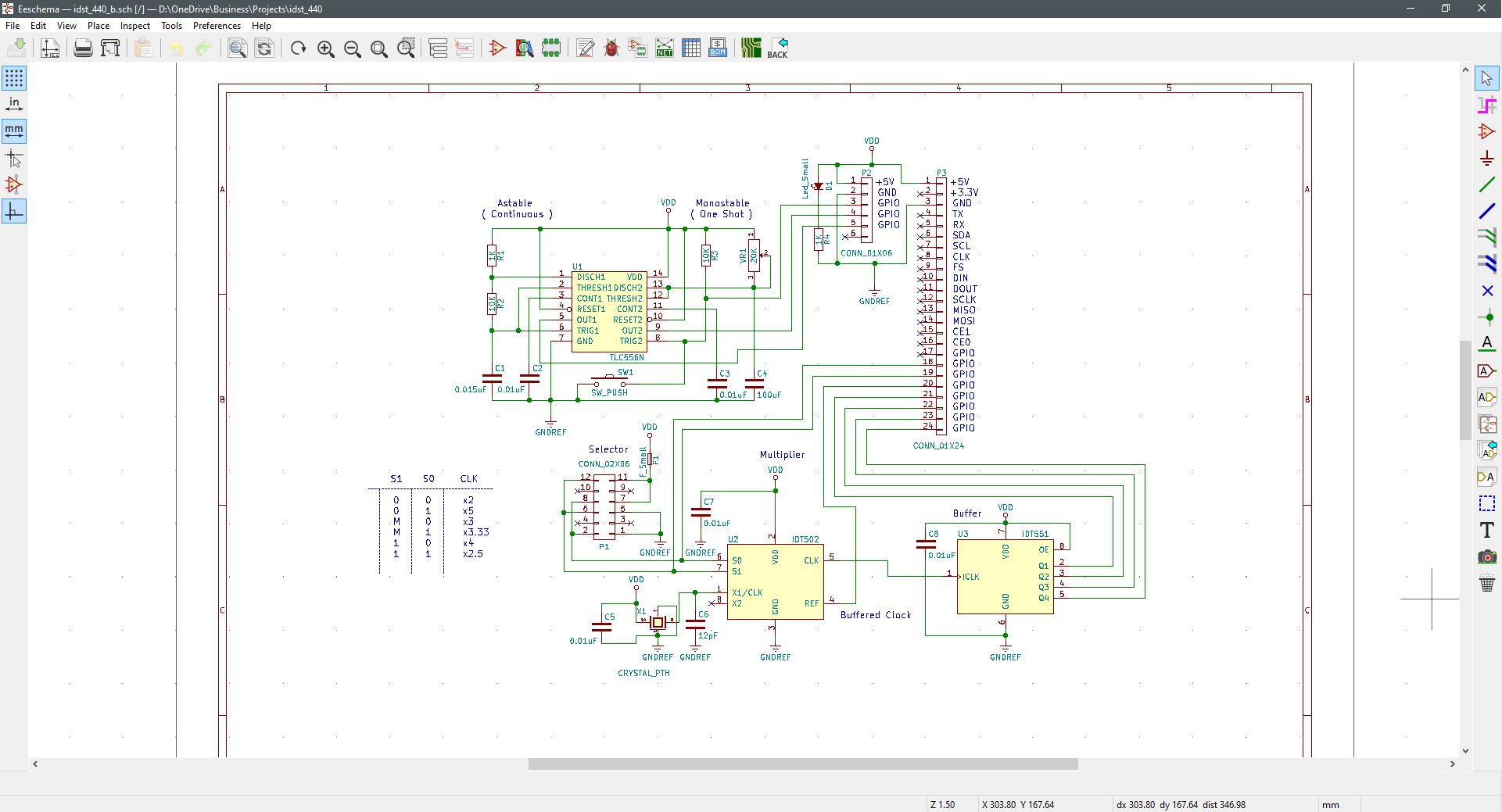
As more circuit builds come about, they’re increasing in density. Bought the parts. Gerber files, drill codes and netlist off to the fabrication house now. The programmable timing module design is finished. With hardware debugging ahead a few minor adjustments are expected once results are validated. This is a mixed-mode project where both plated through-hole and surface mount components are applied.

In a micro-slot format, this is a module intended for use in a free-standing application. With pulse speed and duty cycle setting completed manually via jumpers and a trimmer, separate outputs are assigned to independent and isolated pins at the micro-slot header.

Here is a tentative sketch of what it looks like.

Continue Reading ·

RPi Sensor Station Prototype Evaluation and Debug

Today I finished the RPi 3 shield station prototype. Designed it, built it and the system works right from power-up. All the sensors were loaded and came online. The unit was booted with the Linux prompt to support the code for various sensors. The station is also driving each separate module developed so far as well. It’s also network aware at this location’s WiFi.

At some point, there will be a separate Arduino version of the station, but next up is the ‘universal’ power supply. Then the cooling module, and on over to additional planned modules for integration. 


Continue Reading ·

LED Illumination Control with Arduino Uno

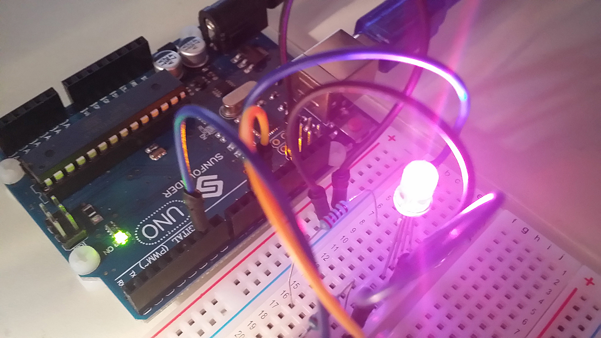
There was an online guide that walks a viewer through how to assign color variable values in code to red, green and blue. To combine each as having relative color strength to produce a mixed color output on an RGB LED. This is a way to prepare unique light color values beyond the conventional LED lights with fixed colors. In this small project, color is programmed within the Arduino IDE and thereafter code loaded into the SBC itself to run the unique color mix.

The code to set up this functionality is set up on Arduino Sketch. To write and edit instructions that determine the operability and behavioral properties of the hardware and circuit.

After declarations and set up, this is what the code looks like.

void loop()
{
Serial.println(“Please input your color choice (red, green or blue): “);
while (Serial.available()==0) {

colorChoice= Serial.readString();

if (colorChoice==”red”)
{analogWrite(redPin,brightness);
analogWrite(bluePin,0);
analogWrite(greenPin,0);
}
if (colorChoice==”green”){
analogWrite(redPin,0);
analogWrite(bluePin,0);
analogWrite(greenPin,brightness);
}
if (colorChoice==”blue”){
analogWrite(redPin,0);
analogWrite(bluePin,brightness);
analogWrite(greenPin,0);
}
if ( colorChoice != “red” && colorChoice != “green” && colorChoice != “blue”) { //test for valid input
Serial.println(“”);
Serial.println(“You have not entered a valid color, please enter red, blue or green”);
Serial.println(“”);
}
}

Continue Reading ·

Power Supply Assembly for SBC Modules

Here is the power supply I made from scratch to support the various modules developed so far. With more to come, this unit is sure to prove useful again and again. A fundamental layer module for various units that are developed; both analog and digital.

This is a power supply module with +/- 15V and +5V output ports. The module hosts a low-profile switching power supply (SPS) soldered and bolted in place for high board retention. At the output of the module is a screw-locking terminal strip for each available voltage point. To include reference designators as printed on the circuit board for ease of identification and termination. The power LED illuminates as an AC input voltage is applied.

An AC source voltage is supported with a male 3-point plug-detachable receptacle for a 115VAC 60Hz input. This unit comes with a matching male plug for safe and fully insulated AC connectivity. The module is fitted with a 3A circuit breaker that provides added protection between the SPS and its source.


Continue Reading ·

4-Channel Signal Relay Board for SBC Modules

This is a video walk-through about a 4-channel contact closure relay module I made. An example application is demonstrated here by driving a micro-fan through a relay and connector signal path via a remote and physically isolated contact closure made at an input. There are many applications by which this module will prove both practical and useful.

It serves as a way to achieve a high-current path closure by simply providing a shorted connection at each input.

https://youtu.be/1FgDOD8vWGQ


Continue Reading ·

Signal Interrupt & Ground Lift Board for SBC Modules

This is a video that explains the purpose and function of the signal interrupt module. This was the first module I developed and made as an effort to get familiar with KiCAD and other development instruments. It is a simple 8-channel 1:1 input to output signal interface unit that provides for signal interrupt and patch capabilities to external devices. The module also supports micro-patch capabilities from numbered input channels to differently designated channels via patch conductors and to 24-pin connector terminals.

Continue Reading ·

Active Thermal Control for SBC Modules

This is a single-board computer (SBC) thermal management module loaded with variable controlled fans. Two manual settings for each fan at either high or low, provide for a steady level of cooling. Enable all fans at high or all at low for either maximum or minimum active cooling. Or assign each fan a high or low setting to get fully custom airflow as a fixed setting.

Conversely, continuously variable fan speed is possible from a sensor attached to each separate fan cooling channel. Each separate fan sensor is a positive temperature coefficient (PTC) thermistor rated at 60˚ Celsius. Attach any or all sensors to a thermally active device and the module increases or decreases assigned fans to an appropriately matched speed for optimum and efficient cooling.

https://youtu.be/x8FHBlYOlsg


Continue Reading ·