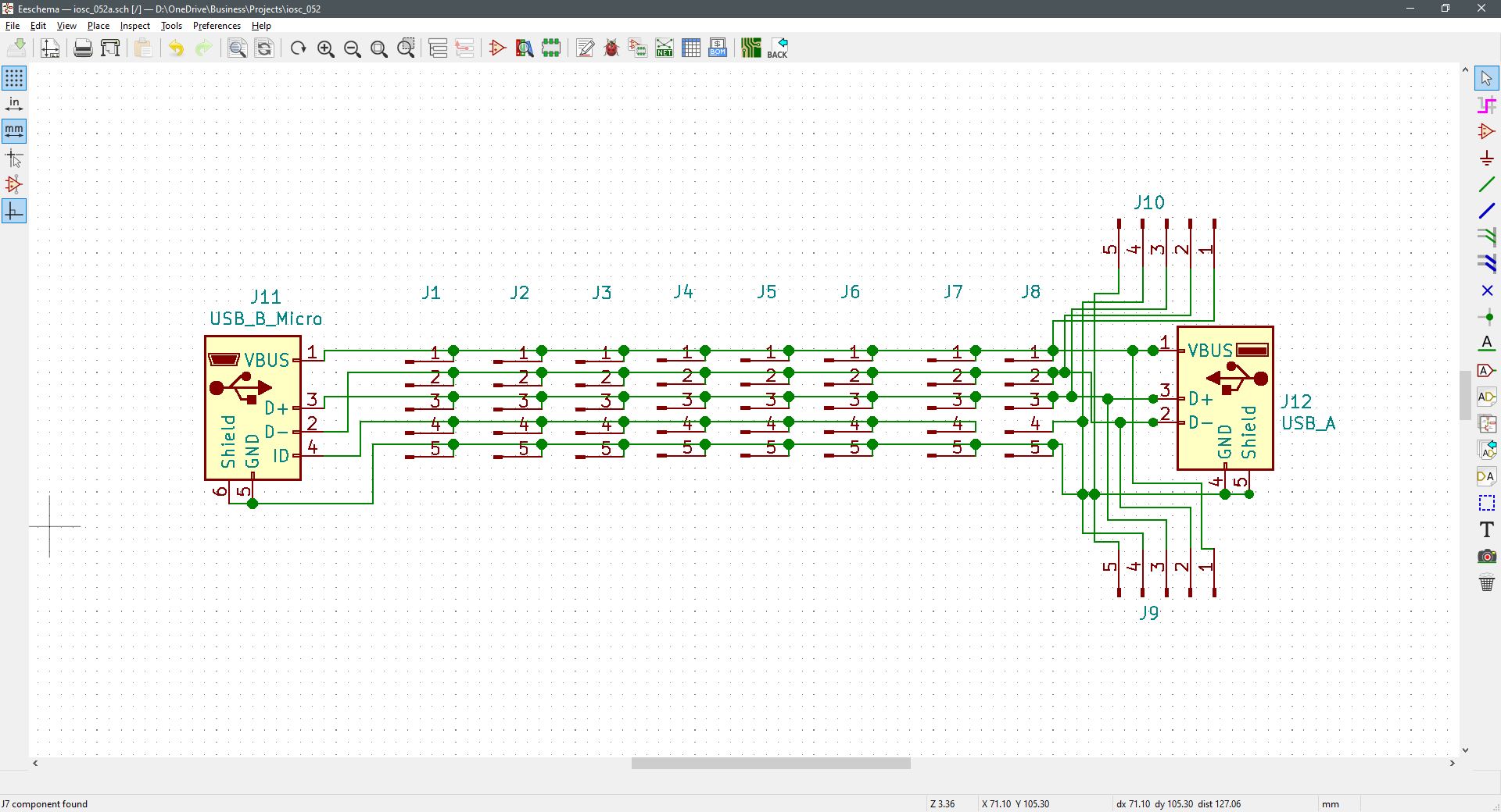
The primary difference with this USB-B Micro breakout module and the earlier developed model is the USB-A receptacle at its output. The J11 input to J12 output is a straight-through except for the Micro-USB path to J8. This connection is severed to assure an output from a connected device doesn’t become unnecessarily grounded. The other side of J8 is connected to both ground and shield to assure pin-4 is grounded as per the USB-A connection standard.
If it is desired or necessary to ground the ID pin along the later connectors J1 through J8, then use a jumper/shunt block. This connection has a standard 0.1″ pin separation.
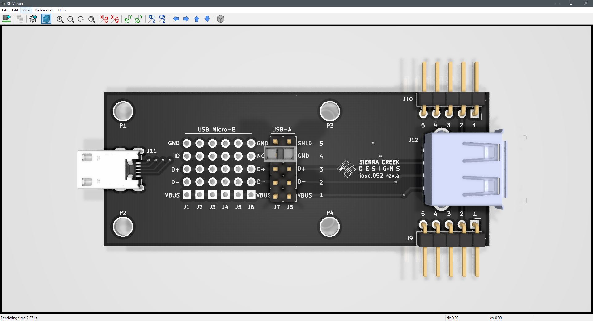
As described earlier, this module only provides for 5-pins including shield terminations. Specifically, pinout connections corresponding to USB 2.0. The input plug extends to the output receptacle with numerous signal and voltage tap points in-between.
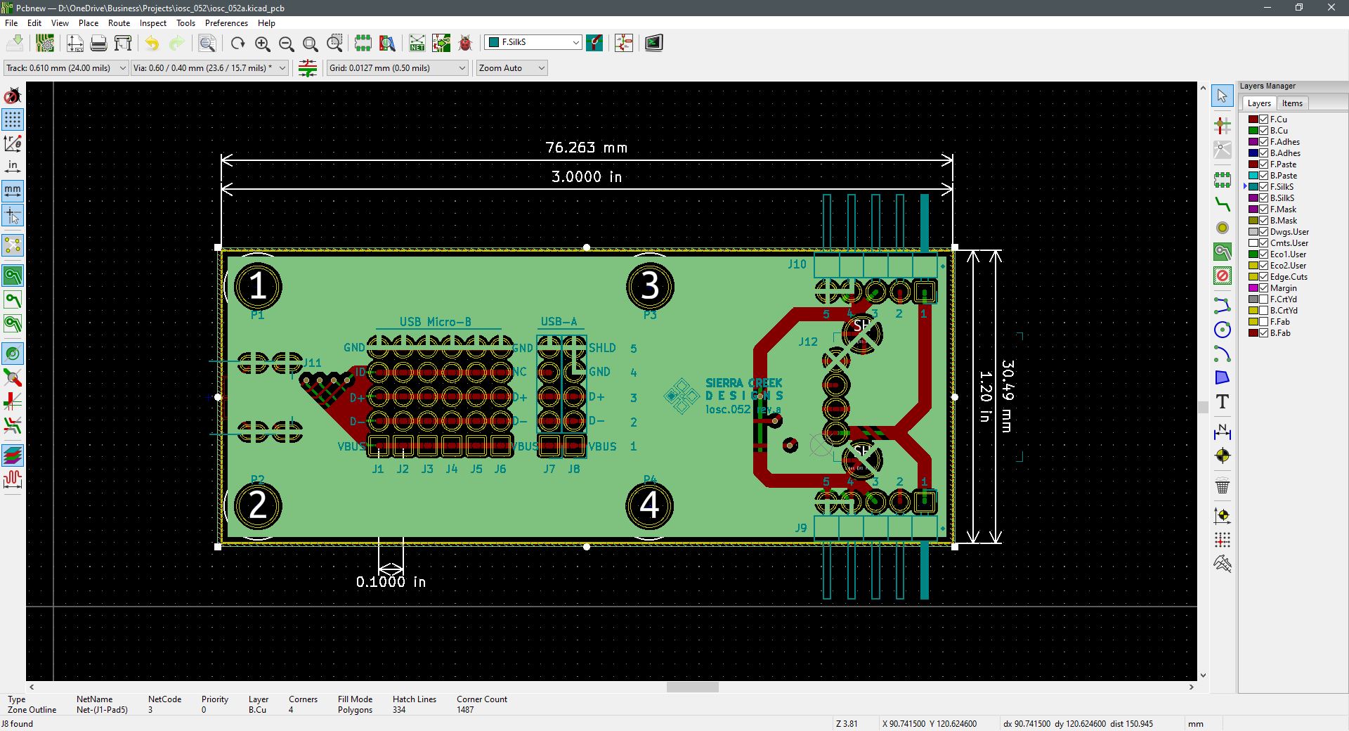
Then as before with the USB-micro break out module, these through-hole connections serve as a grid of tap points for purposes of measurement, or to add an external device for peripheral functions (J1 – J8). The female receptacle is the input at J11 and the other female receptacle is at the output at J12. The 5-pin headers at J9 and J10 are simply in parallel with both the USB plug and receptacle for extended use without the need for solder work at the J1 – J8 header grid. Assuming these pads are mounted with pin-headers.


Comments are closed.