Archive | Projects RSS feed for this section

USB-C Male Breakout Module

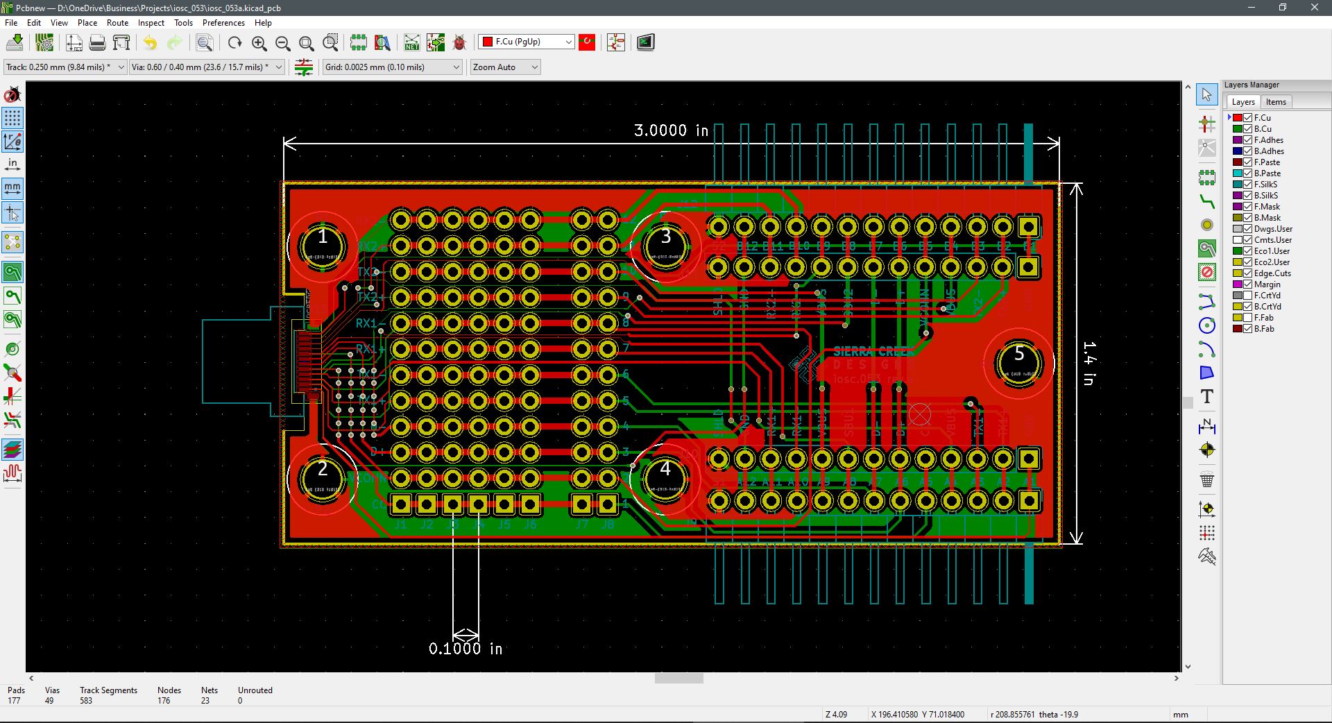
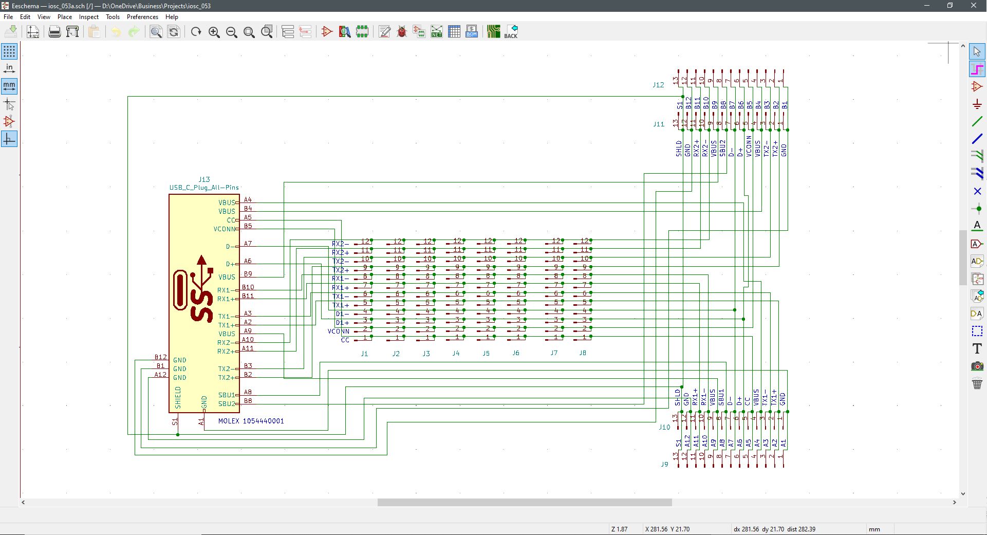
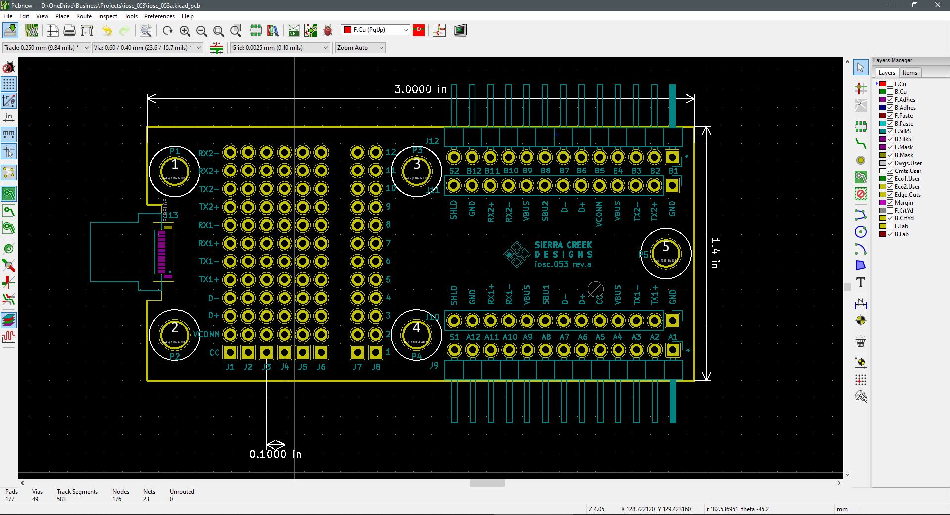
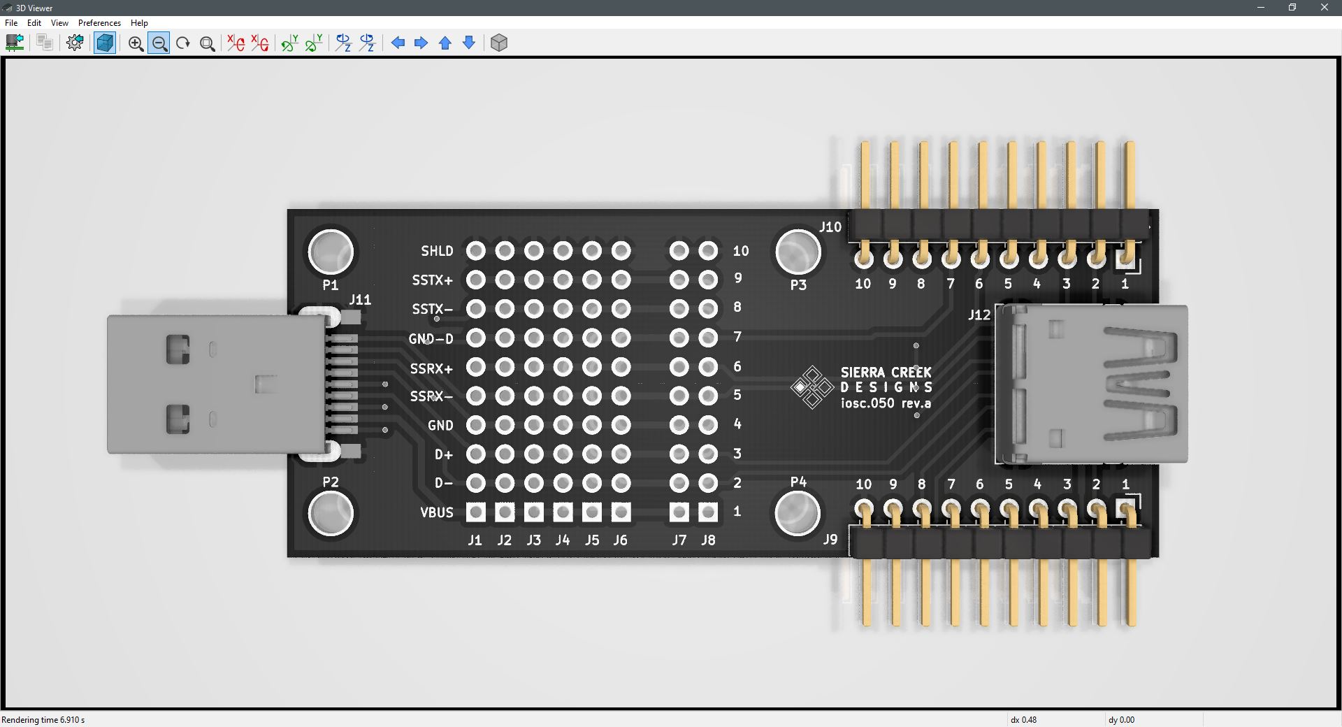
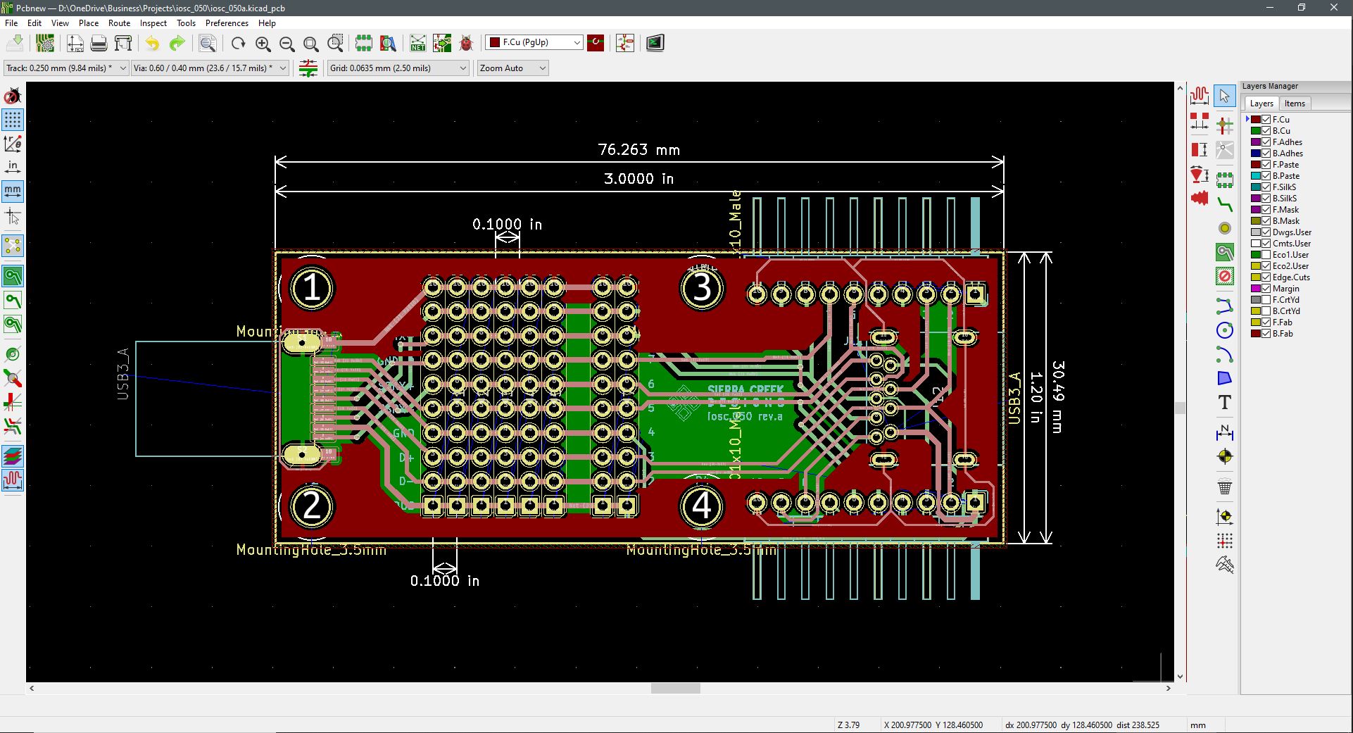
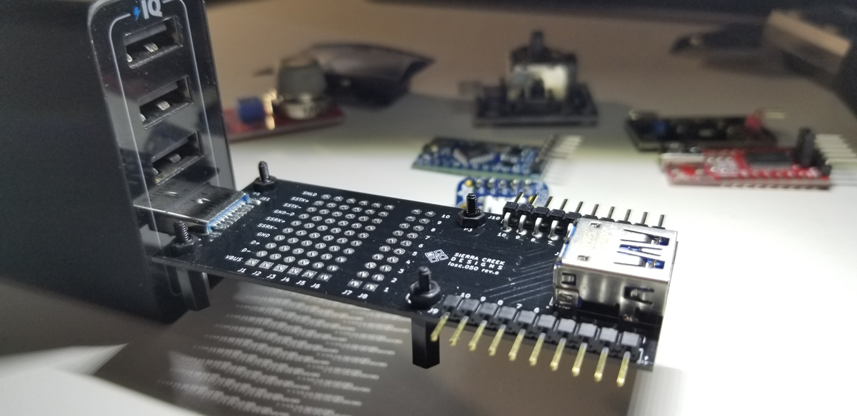
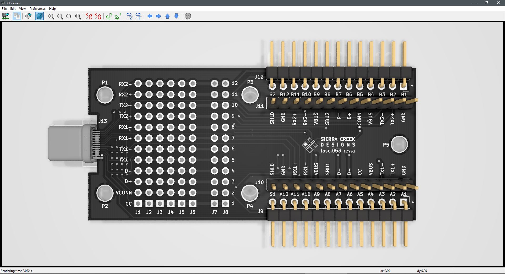
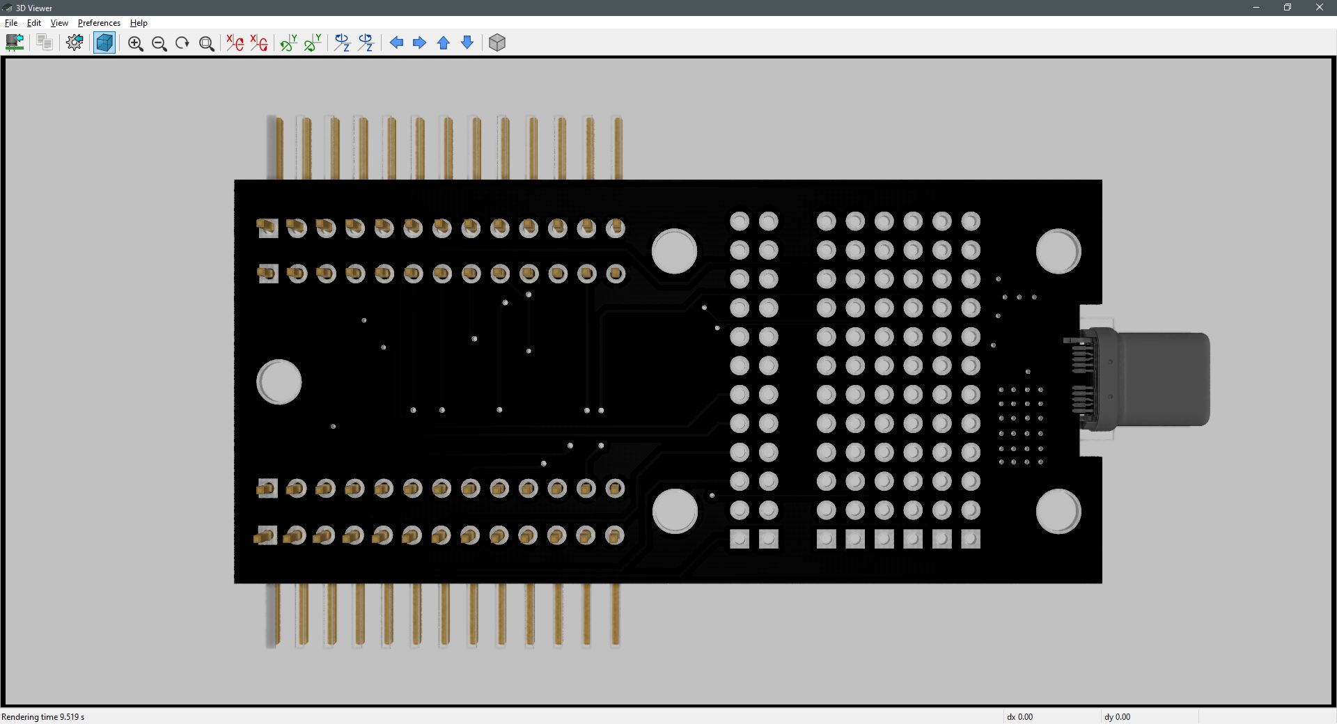
This USB-C breakout module is designed to separate out all pins and the shield of a standard 24-pin USB-C plug connector. As with prior USB breakout modules, each pin is grouped together on a grid for ease of measurement of signal levels and communication. Data and control lines are presented at connectors J1- J8 without VBUS or ground connections. The VBUS, ground, and shield connections are available at the pin-headers J9 – J12. The mounting holes P1 – P5 are connected to the entire shield path among all connections.

Connectors J9 and J10 are in parallel as physical connections to each other. Just the same as J11 and J12. These paired pin-headers are set up this way to support either ribbon cable terminations or perforated board placement while leaving open the pin connections for additional breakout aside from the grid between J1 and J8.
Continue Reading ·

USB-Micro Breakout Module

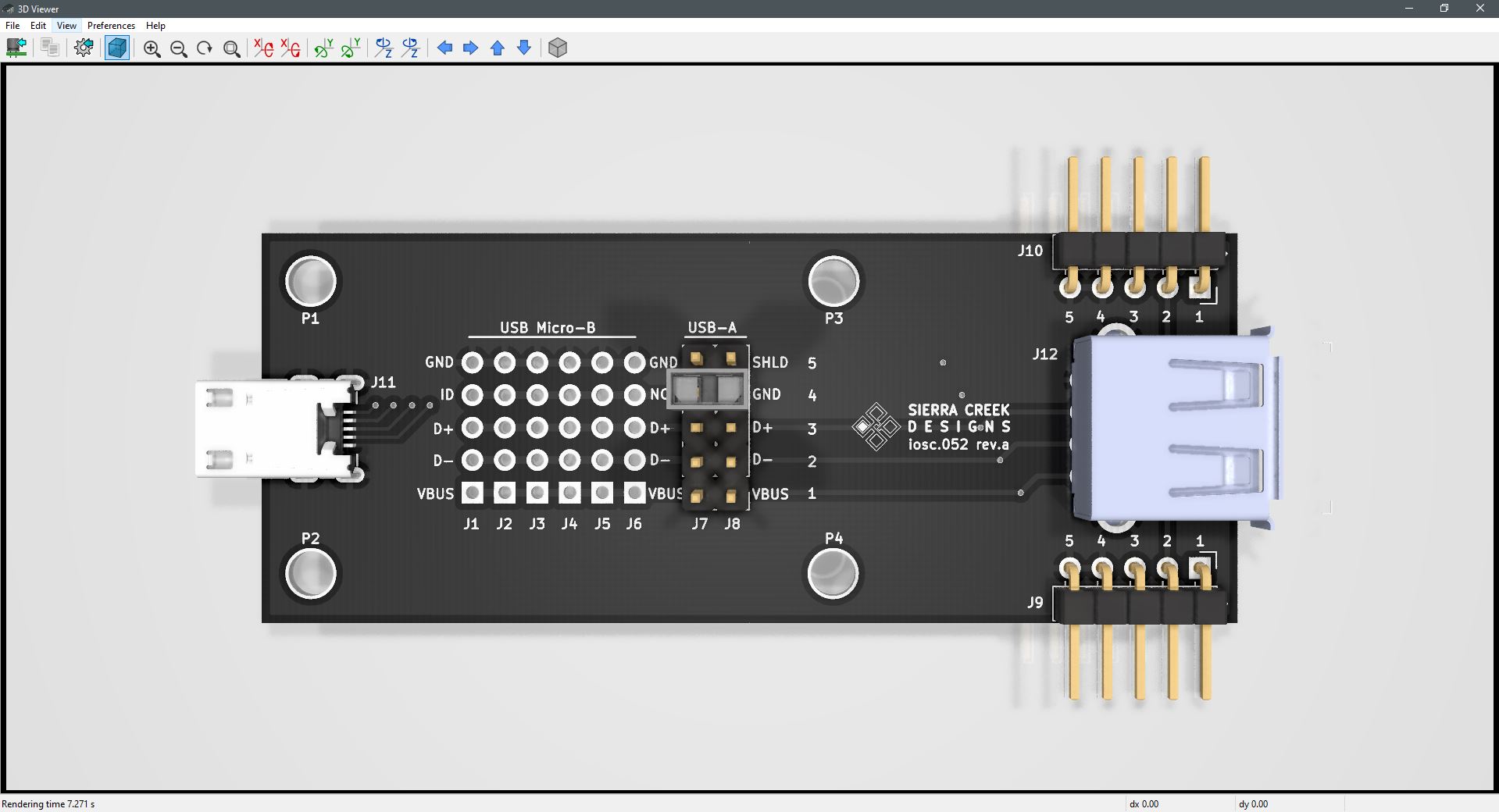
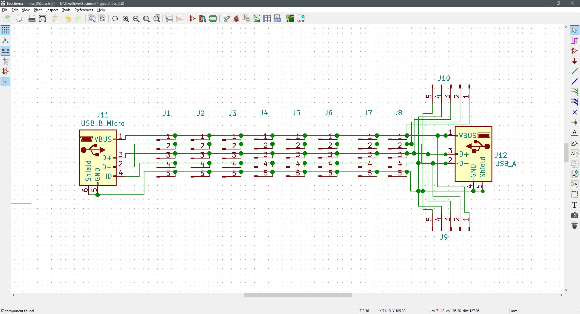
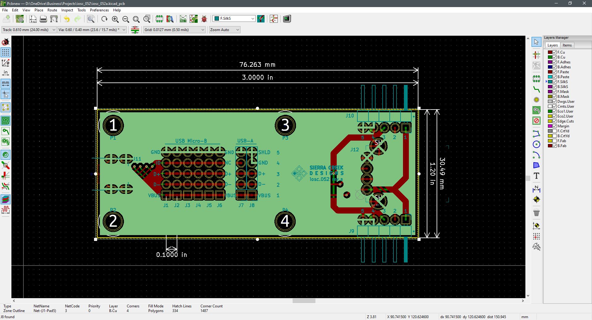
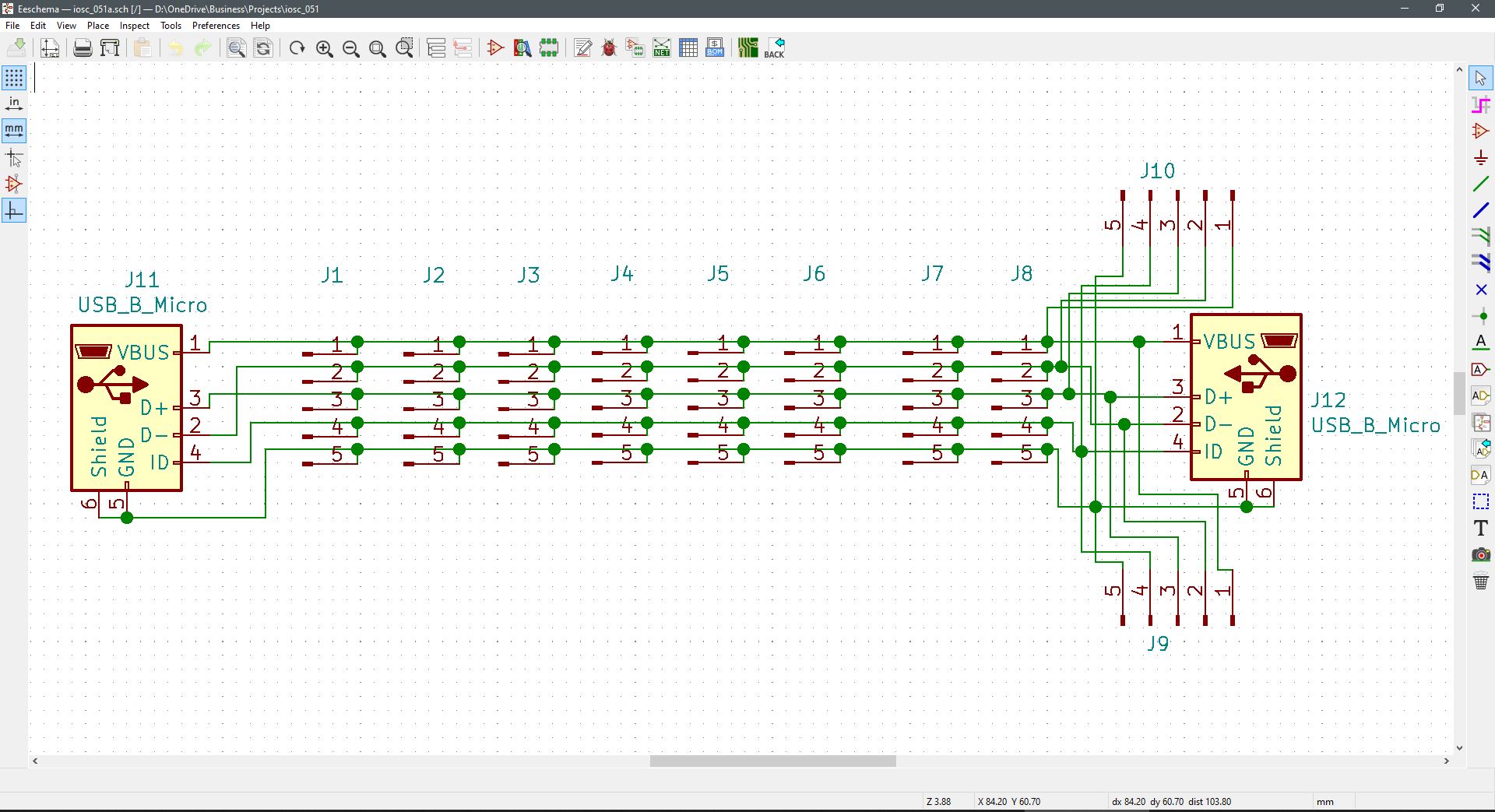
The primary difference with this USB-B Micro breakout module and the earlier developed model is the USB-A receptacle at its output. The J11 input to J12 output is a straight-through except for the Micro-USB path to J8. This connection is severed to assure an output from a connected device doesn’t become unnecessarily grounded. The other side of J8 is connected to both ground and shield to assure pin-4 is grounded as per the USB-A connection standard.

If it is desired or necessary to ground the ID pin along the later connectors J1 through J8, then use a jumper/shunt block. This connection has a standard 0.1″ pin separation.

As described earlier, this module only provides for 5-pins including shield terminations. Specifically, pinout connections corresponding to USB 2.0. The input plug extends to the output receptacle with numerous signal and voltage tap points in-between.

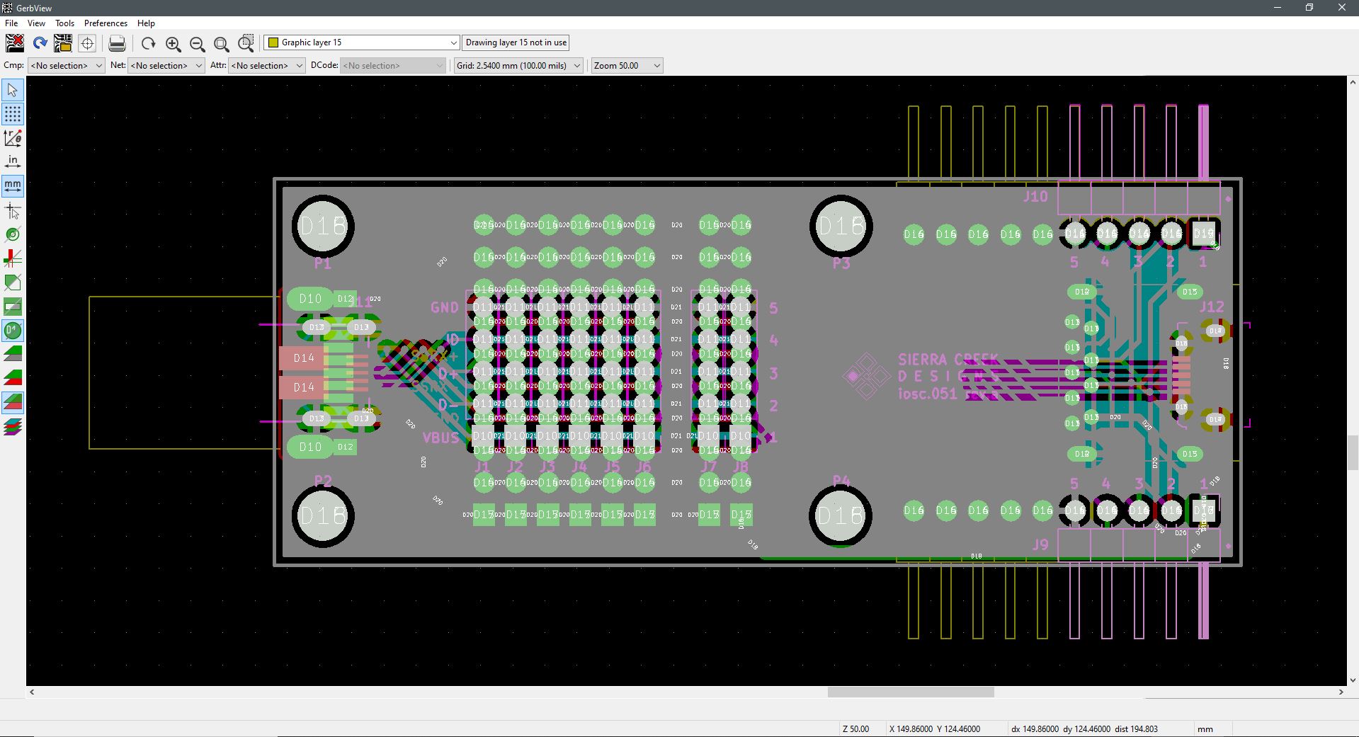
Then as before with the USB-micro break out module, these through-hole connections serve as a grid of tap points for purposes of measurement, or to add an external device for peripheral functions (J1 – J8). The female receptacle is the input at J11 and the other female receptacle is at the output at J12. The 5-pin headers at J9 and J10 are simply in parallel with both the USB plug and receptacle for extended use without the need for solder work at the J1 – J8 header grid. Assuming these pads are mounted with pin-headers.


Continue Reading ·

USB-B Breakout Module

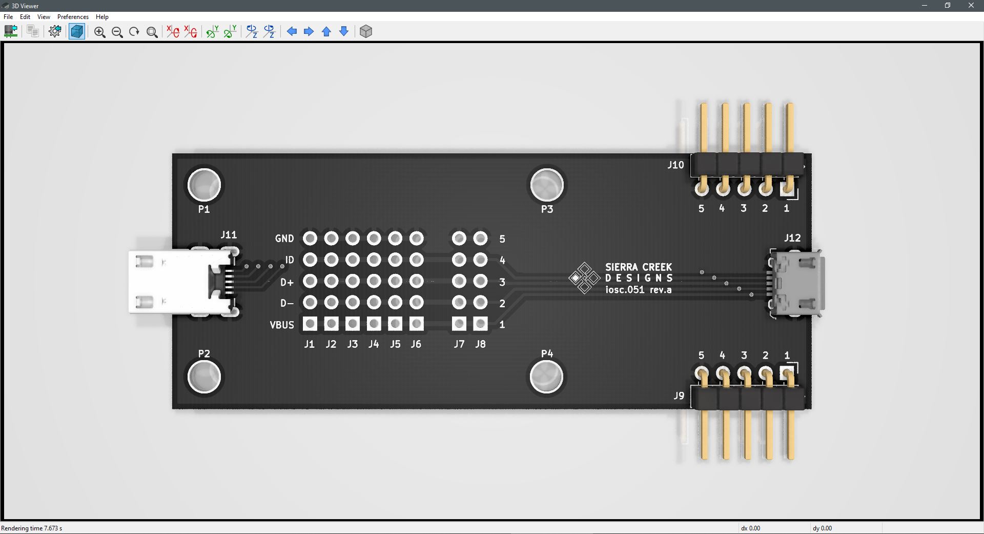
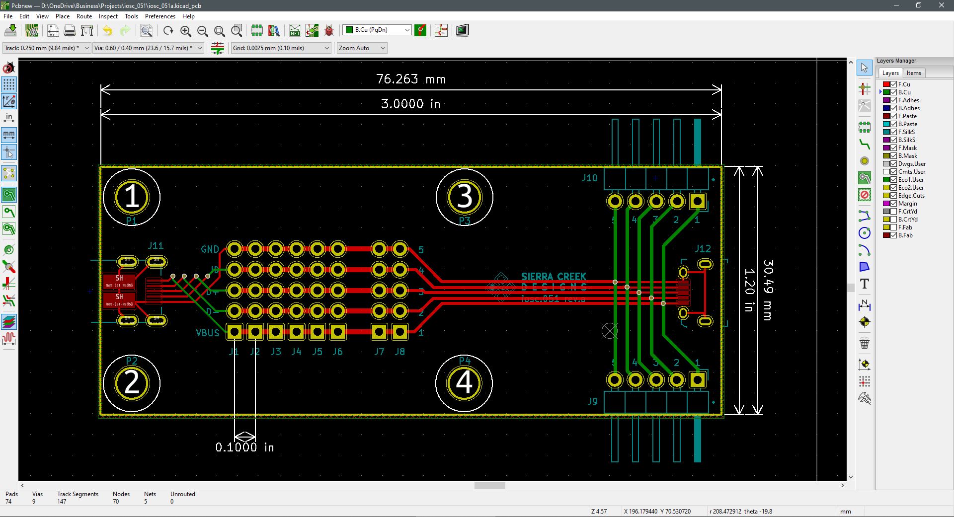
This USB Micro-B breakout module is sort of a little brother of the USB-A 10-pin breakout module designs and developed earlier. This module only provides for 5-pins including shield terminations. Specifically, pinout connections corresponding to USB 2.0. The input plug extends to the output receptacle with numerous signal and voltage tap points in-between.

As before with the USB-A break out module, these through-hole connections serve as a grid of tap points for purposes of measurement, or to add an external device for peripheral functions (J1 – J8). The female receptacle is the input at J11 and the other female receptacle is the output at J12. The 5-pin headers at J9 and J10 are simply in parallel with both the USB plug and receptacle for extended use without the need for solder work at the J1 – J8 header grid.

Continue Reading ·

USB-A Breakout Module

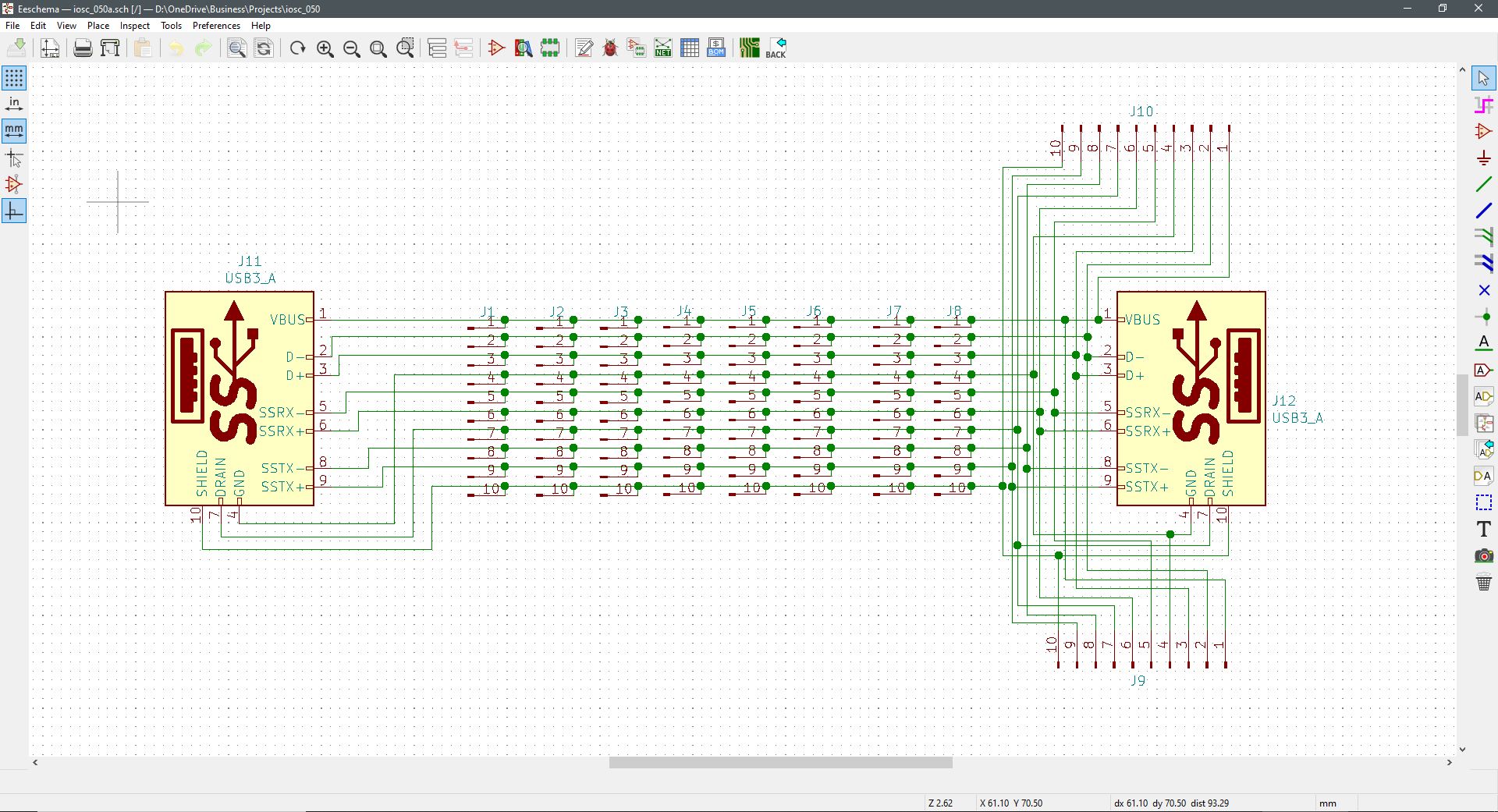
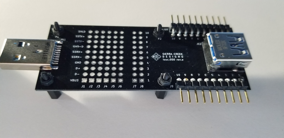
Setting up this breakout module for connectivity between a USB receptacle and a USB plug required careful attention to detail. It was necessary to pay attention to numerous factors concerning layout, component positioning, dimensioning, and port orientation. The selection of both USB connectors was somewhat tentative because of a concern for anchoring to the PCB where there is sufficient strain relief from angular forces applied to each end. Ultimately, both USB connectors chosen were through-hole to assure a secure enough physical connection. The two 0.1″ pin headers on each end correlate to the 10-pin USB3.0/3.1 pin assignments by name and number.

While the array of pads (J1 – J8) is in place to tap off signal, power, and ground points along the USB path, the two pin headers are hardwired in to support an electronic breadboard or perforated board mount for convenient solderability. The pin headers J9 and J10 support a vertical mount arrangement, or horizontal, depending upon the project or use-case.

Between the USB connectors, it was necessary to route the data and high-speed traces at roughly equal length distribution and copper thickness. This helps to assure there are no unnecessary voltage level losses and unwanted heat stresses. While this module doesn’t support the data rate specification associated with the SuperSpeed standard, it does support up to 1.0A DC of current from the USB connector power pins (USB 3.0 SuperSpeed at 5Gbit/s; also known as USB 3.1 Gen 1 SuperSpeed at 5Gbit/s; USB 3.1 Gen 2 is SuperSpeed+ with a transfer rate of 10Gbit/s). USB 3.0 SuperSpeed at 5Gbit/s; also known as USB 3.1 Gen 1 SuperSpeed at 5Gbit/s; USB 3.1 Gen 2 is SuperSpeed+ with a transfer rate of 10Gbit/s. This module is connection compatible with USB 1.0 to USB 3.1, but it is not rated for SuperSpeed performance. Largely due to the cost and scope of setting up impedance matching along the data lines with multiple isolated layers of PCB fabrication.

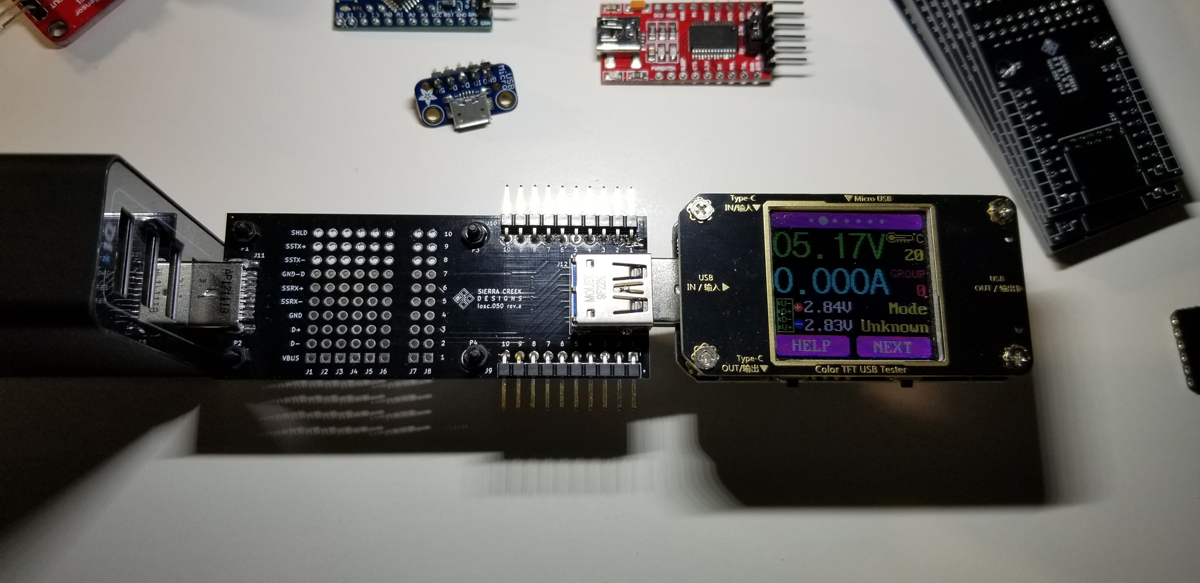
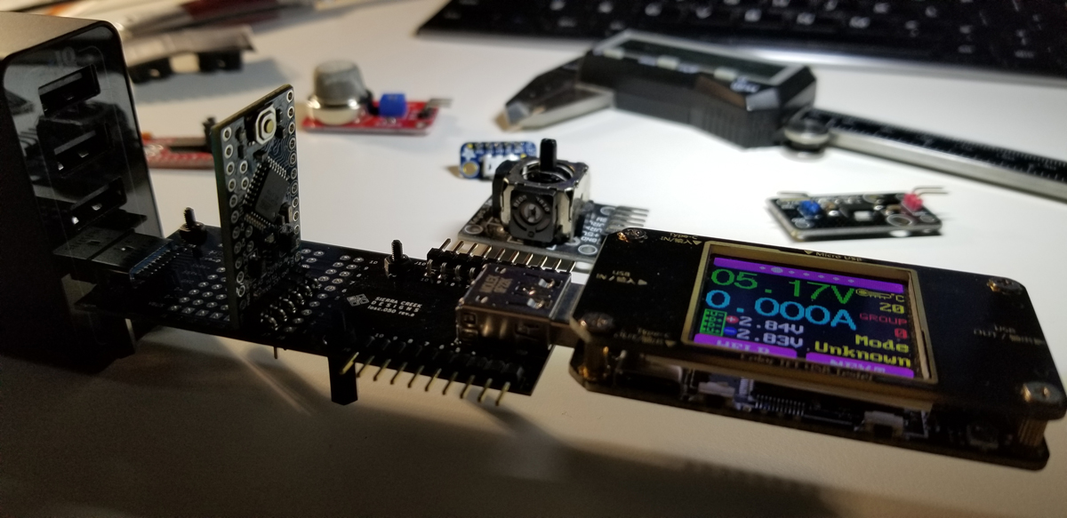
The purpose of this module is to provide a convenient path between two USB ports for utility or experimental reasons. If a user wishes to measure or branch off the pads or pins along a USB path, the freedom is made possible with this module to do that. Either by inserting a small bed-of-nails or by attaching through-hole parts and pins as desired.

Continue Reading ·

Signal Breakout – Terminal

This module is identically the same as the 2.5mm breakout module, except the output connection is a 3-position terminal block output. This is a different module to accommodate a twisted-pair wire connection. To review the 2.5mm module, here is its description to cover relevant details for this terminal block version.

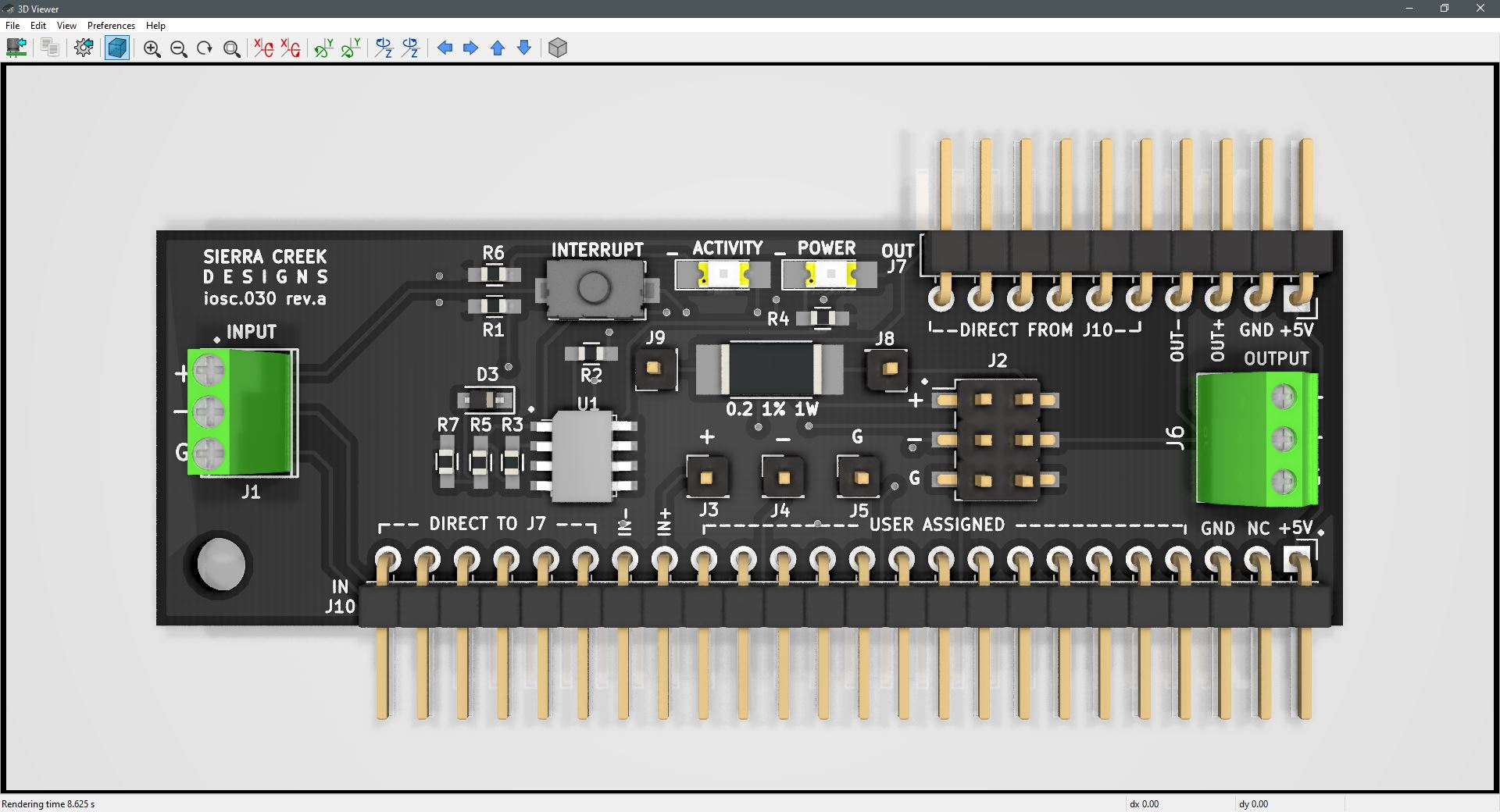
This breakout module is a micro slot module that permits the interrupt and measurement, capture, and tap of a small highspeed signal. From as low as 10Hz to millions of cycles (>3MHz), a signal’s strength is monitored, cut, interrupted, or redirected. It also supports polarity reversal from input to output. The signal output is connected to either the 2.5mm barrel output receptacle or the pin header at J7.

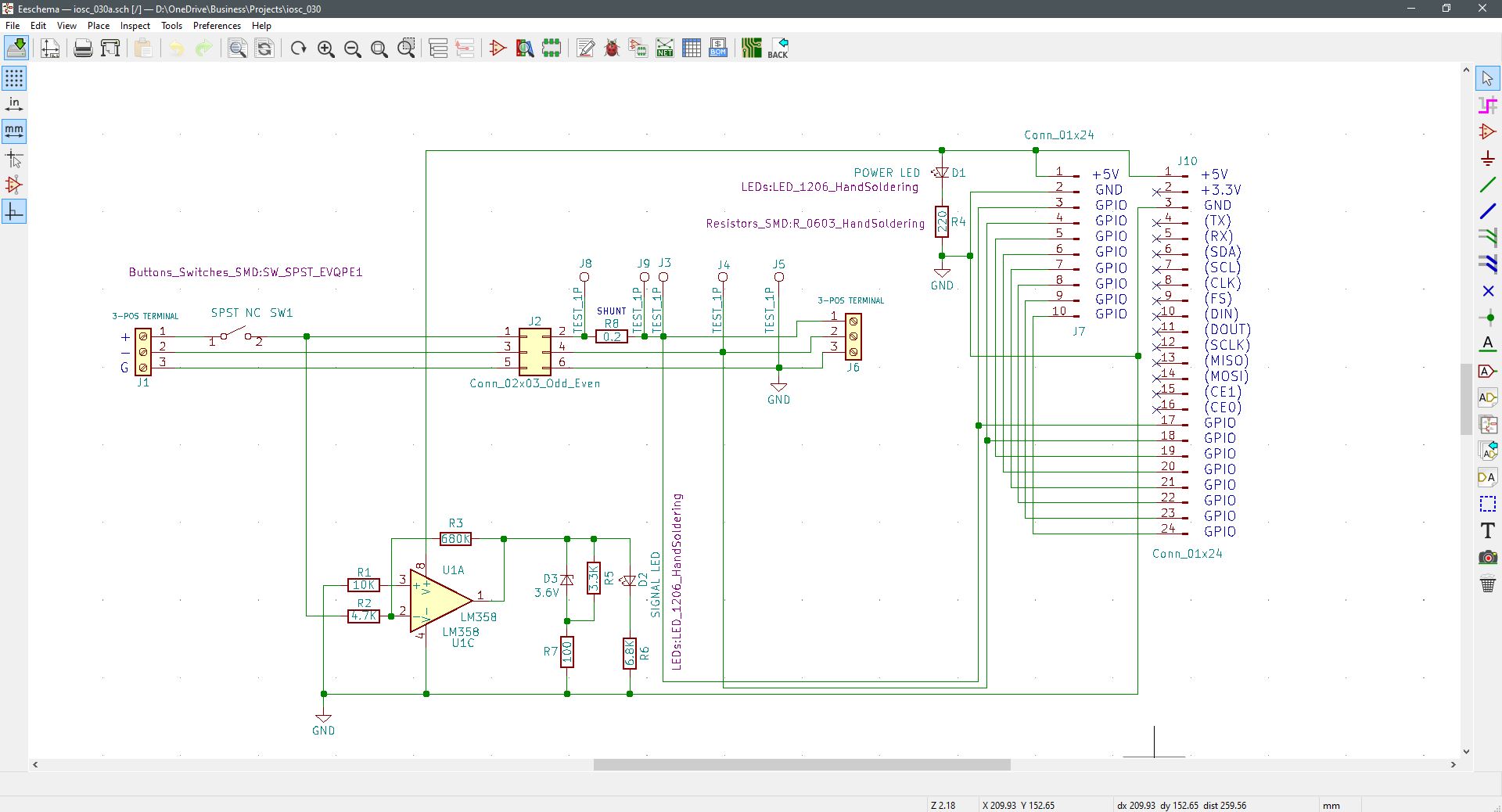
The module also supports current measurement through the 0.2-ohm shunt resistor or voltage capture by any available test point. An input signal’s frequency, phase, polarity, current, voltage, and activity are all observable functions made present on this module. The module also provides for a power presence LED.

The bed-of-nails at J2 is loaded with jumper blocks to complete a signal path. This connector is the point of interrupt for any device to locate in-between the input and output. Remove a jumper block for device insertion. Or remove the jumper block from the ground pins at J2 to serve as a ground lift for a floating and balanced connection. This module is a sort of swiss-army-knife of breakout boards for small signal devices.


Continue Reading ·

Signal Breakout – 3.5mm

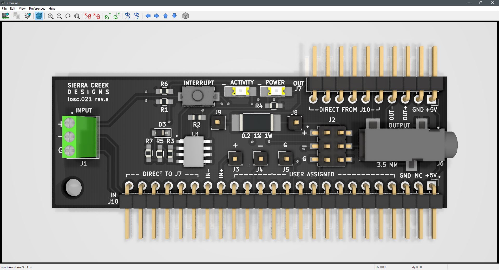
This module is identically the same as the 2.5mm breakout module, except the output connection is a 3.5mm barrel receptacle. This is a different module to accommodate a standard audio connection. To review the 2.5mm module, here is its description to cover relevant details for the 3.5mm version.

This breakout module is a micro slot module that permits the interrupt and measurement, capture, and tap of a small highspeed signal. From as low as 10Hz to millions of cycles (>3MHz), a signal’s strength is monitored, cut, interrupted, or redirected. It also supports polarity reversal from input to output. The signal output is connected to either the 2.5mm barrel output receptacle or the pin header at J7.

The module also supports current measurement through the 0.2-ohm shunt resistor or voltage capture by any available test point. An input signal’s frequency, phase, polarity, current, voltage, and activity are all observable functions made present on this module. The module also provides for a power presence LED.

The bed-of-nails at J2 is loaded with jumper blocks to complete a signal path. This connector is the point of interrupt for any device to locate in-between the input and output. Remove a jumper block for device insertion. Or remove the jumper block from the ground pins at J2 to serve as a ground lift for a floating and balanced connection. This module is a sort of swiss-army-knife of breakout boards for small signal devices.

Continue Reading ·

Signal Breakout – 2.5mm

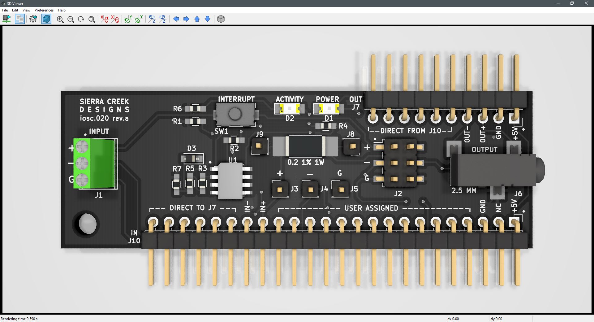
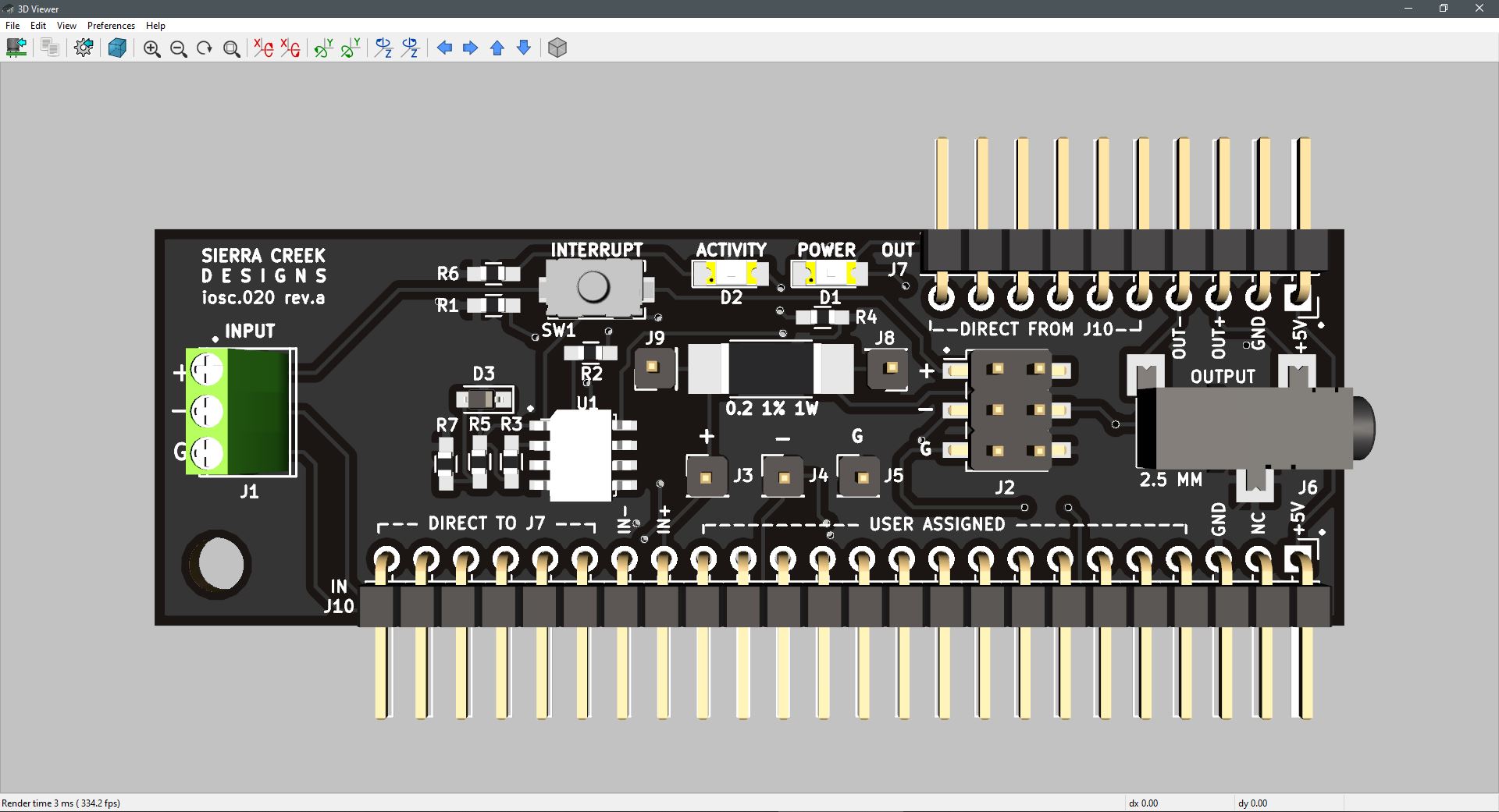
The 2.5mm breakout module is a micro slot module that permits the interrupt and measurement, capture, and tap of a small highspeed signal. From as low as 10Hz to millions of cycles (>3MHz), a signal’s strength is monitored, cut, interrupted, or redirected. It also supports polarity reversal from input to output. The signal output is connected to either the 2.5mm barrel output receptacle or the pin header at J7.

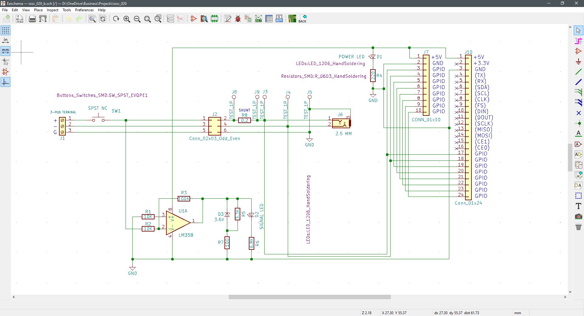
The module also supports current measurement through the 0.2-ohm shunt resistor or voltage capture by any available test point. An input signal’s frequency, phase, polarity, current, voltage, and activity are all observable functions made present on this module. The module also provides for a power presence LED.

The bed-of-nails at J2 is loaded with jumper blocks to complete a signal path. This connector is the point of interrupt for any device to locate in-between the input and output. Remove a jumper block for device insertion. Or remove the jumper block from the ground pins at J2 to serve as a ground lift for a floating and balanced connection. This module is a sort of swiss-army-knife of breakout boards for small signal devices.

Continue Reading ·

Contact Closure Relay Module

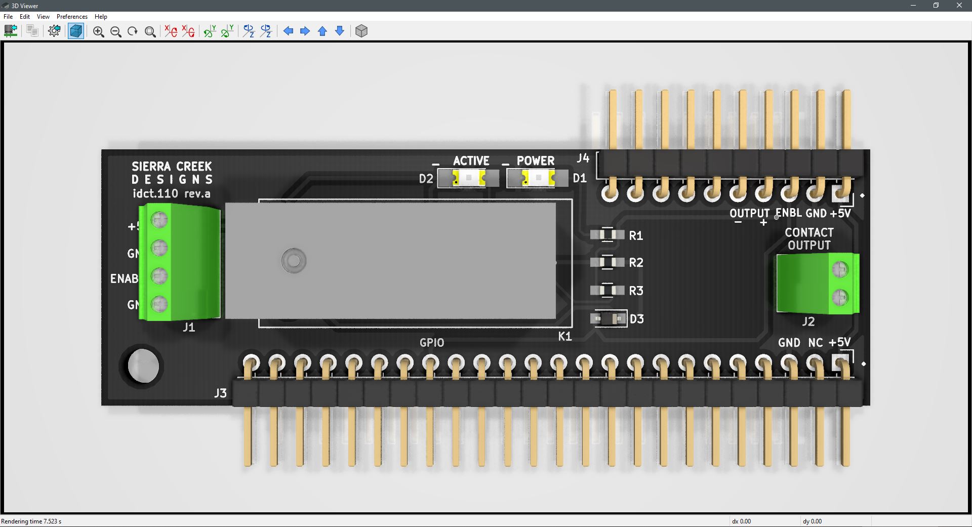
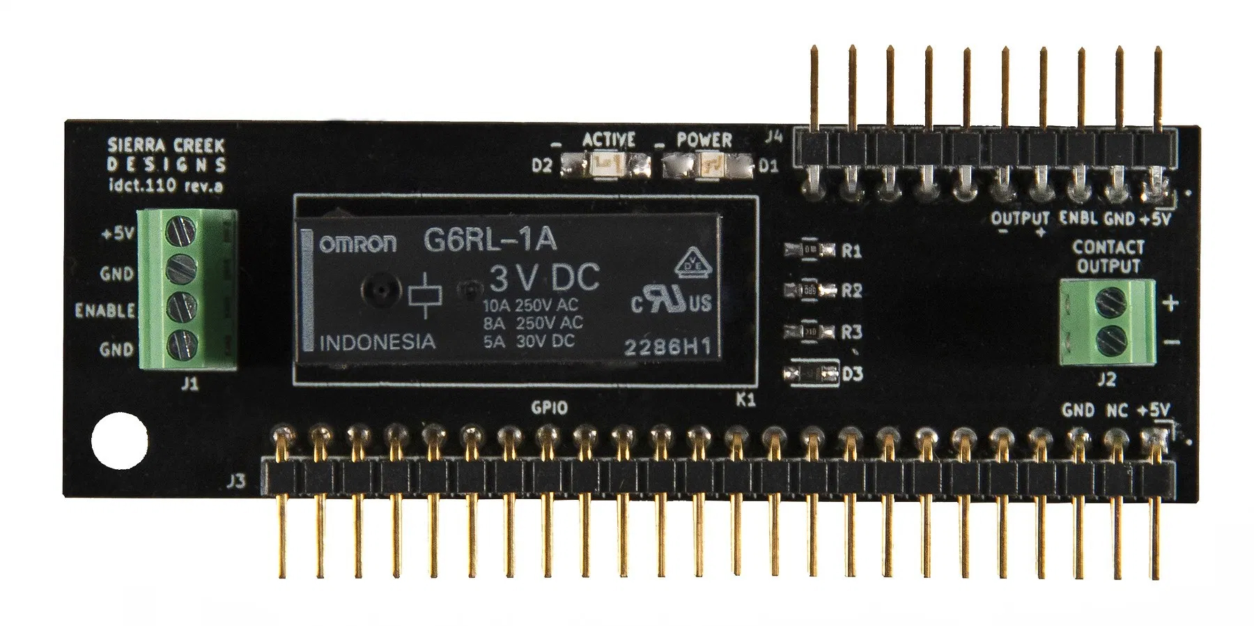
The newly developed micro slot module platform affords more opportunities to bring about new and useful functions. Namely, to support specific capabilities aside from the prior micro slot modules designed to help signal transfer and breakout. Left-to-right input-to-output features for both control and signal transfer or routing, but now also new processes following the same type of transfer function.

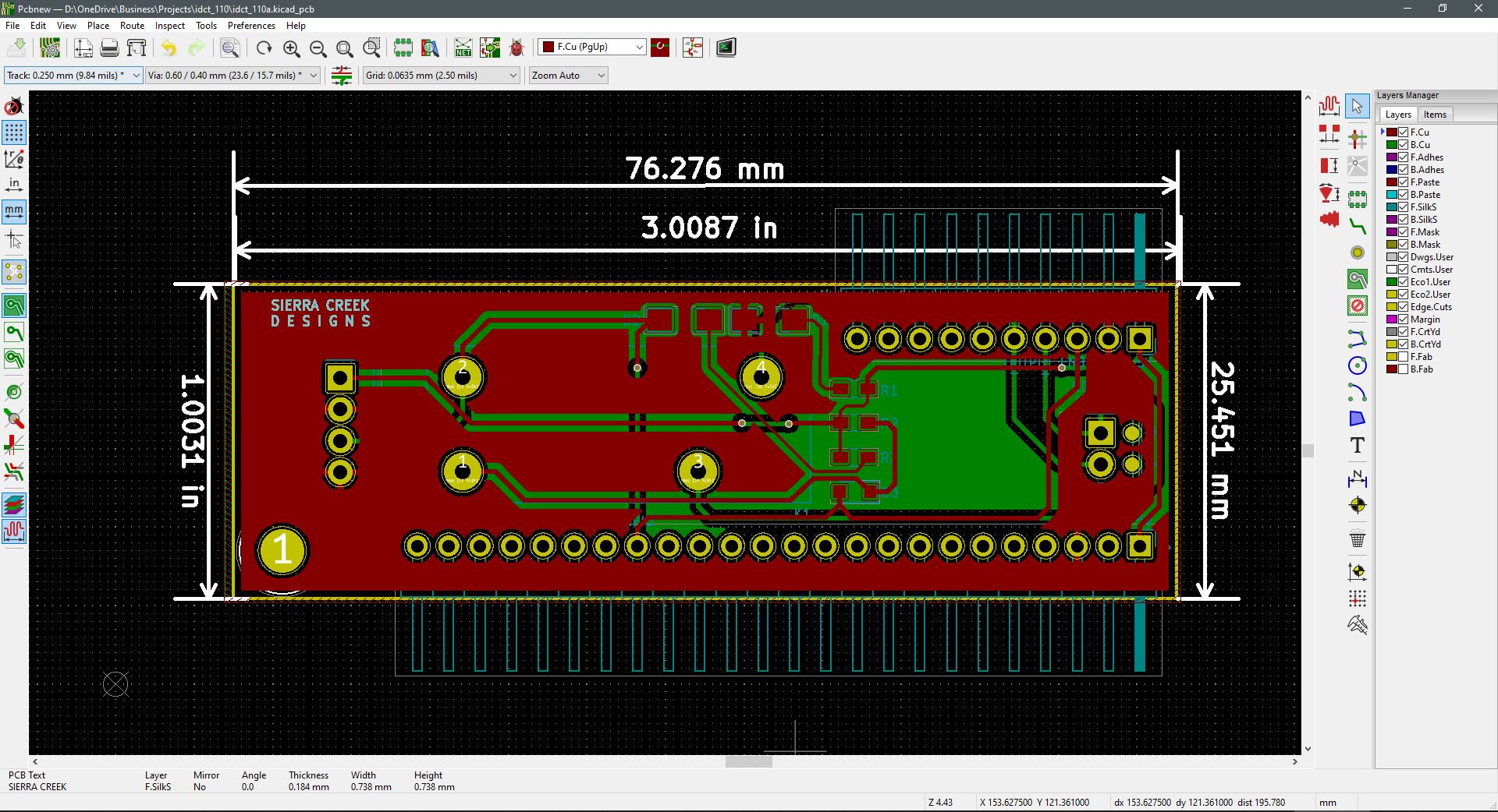
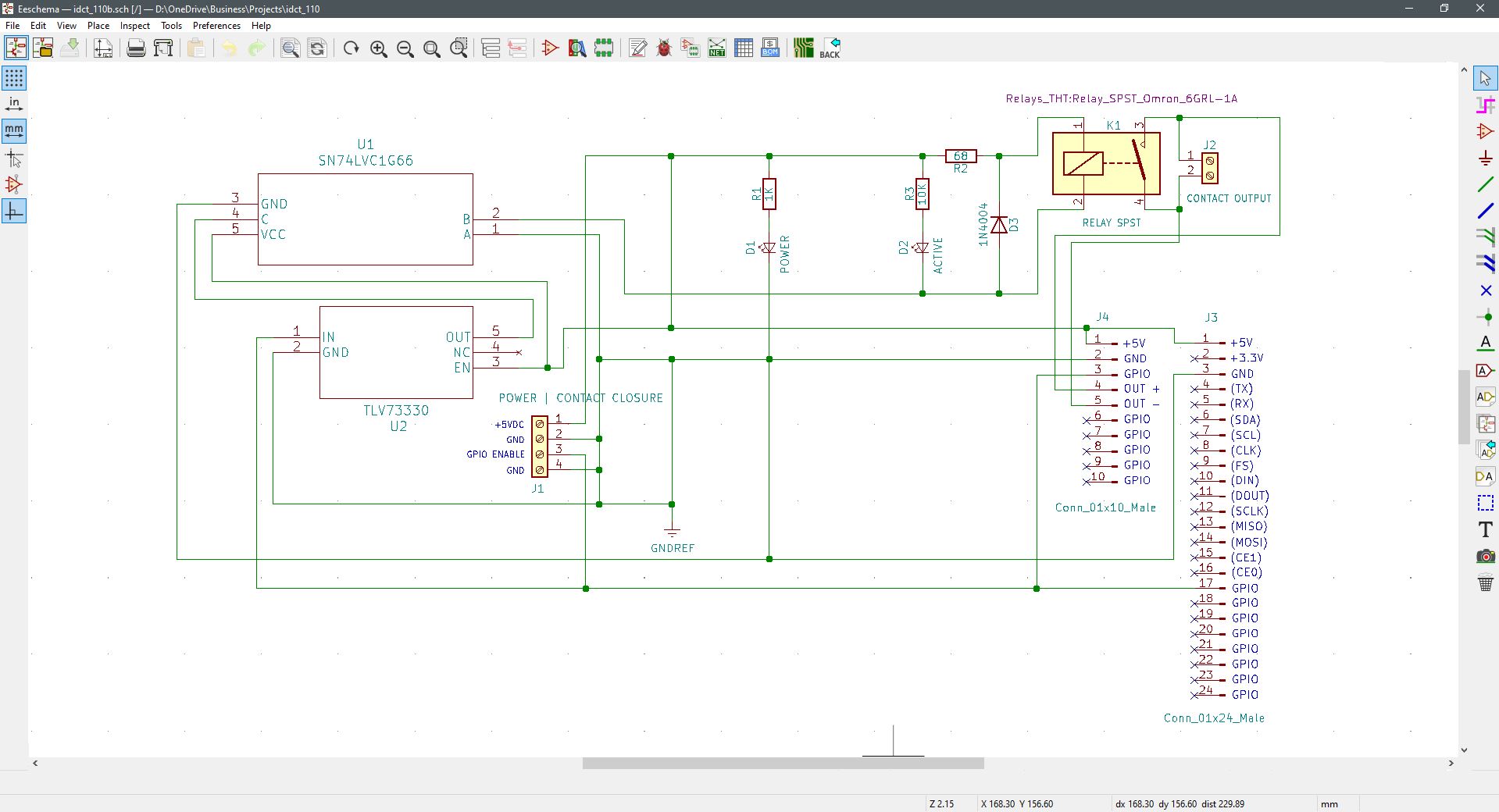
This signal relay module is designed to support a contact closure source to allow a higher current contact path at the module’s output. When a short-circuit path is made at the Enable terminals of the module’s input connector, a relay closure event is triggered at the output. This event provides for a parallel bypass path across an attached load connected to the output connector. Or a series circuit path completion is made to allow a signal or voltage to become active at the output connector.

When the relay module is supplied with 5V; a green LED illuminates to give a user continuous visual Power status. A separate blue Activity LED indicates when the relay itself is enabled by the presence of a contact closure input. As a 5V source is applied to the micro slot module, a simple wire connection from Enable to Ground triggers the relay to complete the output connection path, which in turn illuminates the power Active LED.

Features and capabilities are outlined here to summarize what functions are available.

  • Signal Bypass
  • Circuit Closure
  • Relay Status LED
  • Power Status LED
  • Terminal Block Connectivity
  • Functional Control via Pin Headers

Continue Reading ·