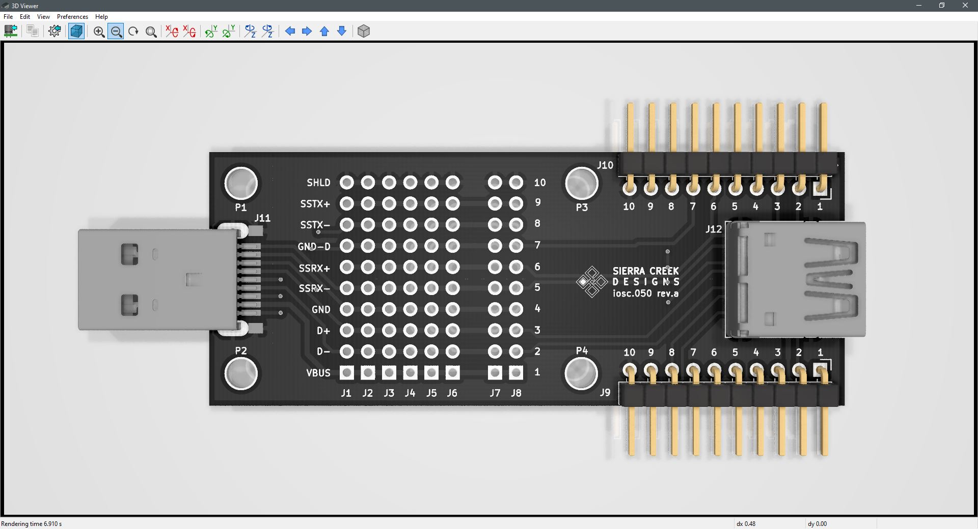
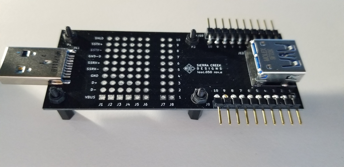
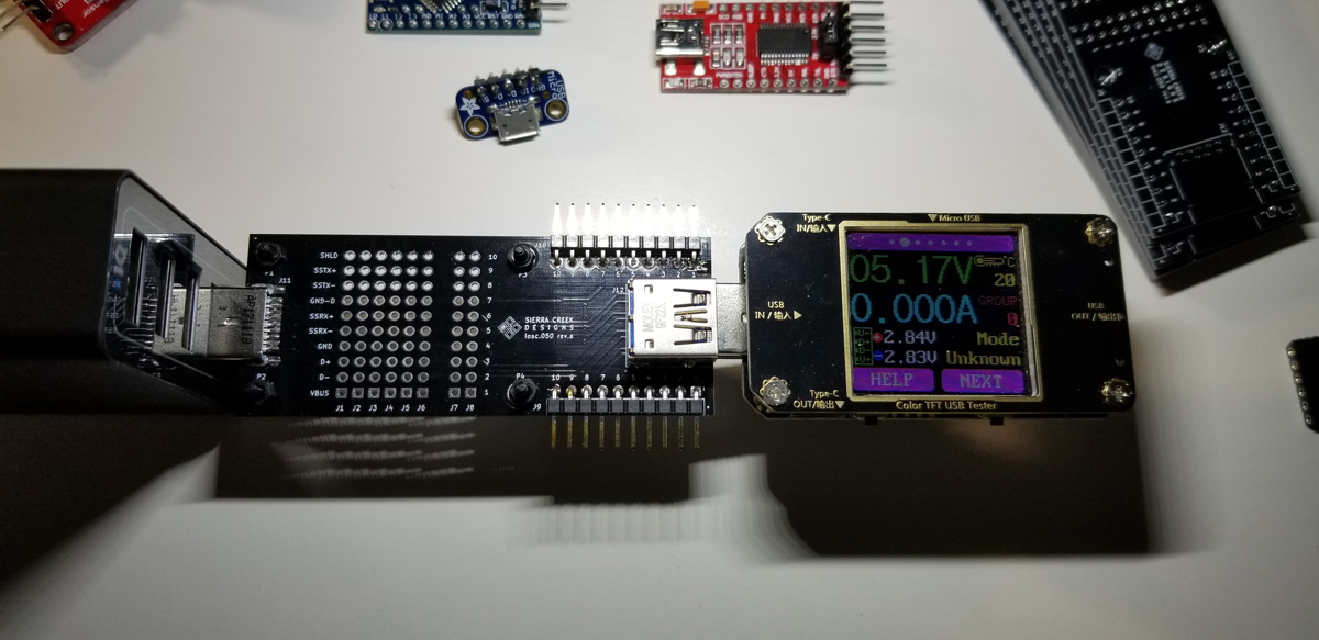
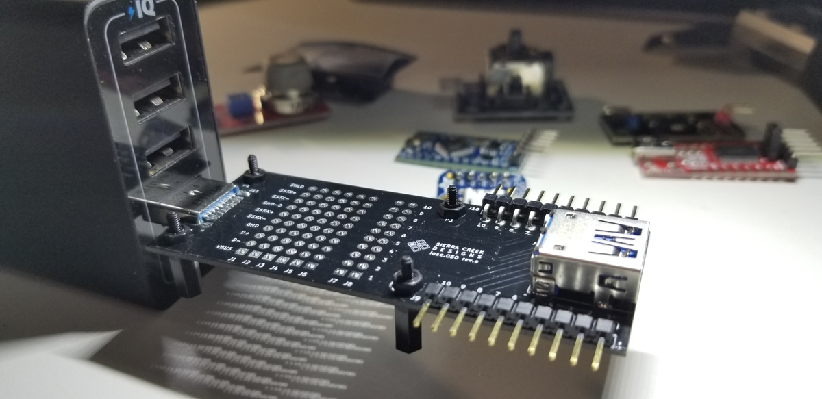
Setting up this breakout module for connectivity between a USB receptacle and a USB plug required careful attention to detail. It was necessary to pay attention to numerous factors concerning layout, component positioning, dimensioning, and port orientation. The selection of both USB connectors was somewhat tentative because of a concern for anchoring to the PCB where there is sufficient strain relief from angular forces applied to each end. Ultimately, both USB connectors chosen were through-hole to assure a secure enough physical connection. The two 0.1″ pin headers on each end correlate to the 10-pin USB3.0/3.1 pin assignments by name and number.
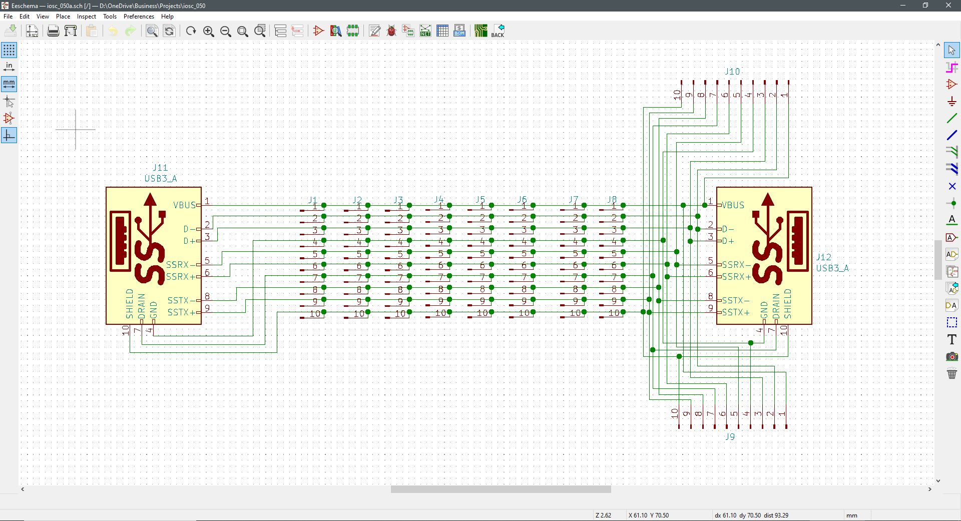
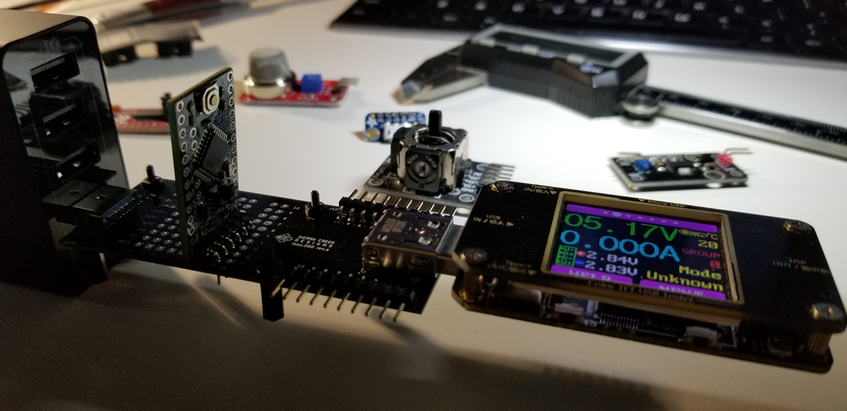
While the array of pads (J1 – J8) is in place to tap off signal, power, and ground points along the USB path, the two pin headers are hardwired in to support an electronic breadboard or perforated board mount for convenient solderability. The pin headers J9 and J10 support a vertical mount arrangement, or horizontal, depending upon the project or use-case.
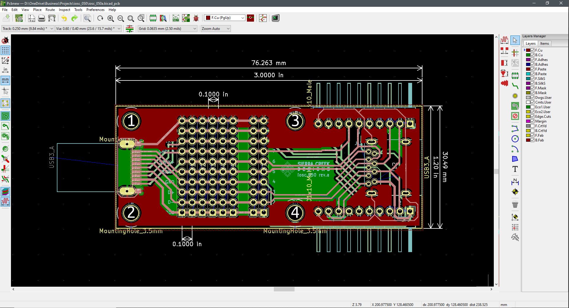
Between the USB connectors, it was necessary to route the data and high-speed traces at roughly equal length distribution and copper thickness. This helps to assure there are no unnecessary voltage level losses and unwanted heat stresses. While this module doesn’t support the data rate specification associated with the SuperSpeed standard, it does support up to 1.0A DC of current from the USB connector power pins (USB 3.0 SuperSpeed at 5Gbit/s; also known as USB 3.1 Gen 1 SuperSpeed at 5Gbit/s; USB 3.1 Gen 2 is SuperSpeed+ with a transfer rate of 10Gbit/s). USB 3.0 SuperSpeed at 5Gbit/s; also known as USB 3.1 Gen 1 SuperSpeed at 5Gbit/s; USB 3.1 Gen 2 is SuperSpeed+ with a transfer rate of 10Gbit/s. This module is connection compatible with USB 1.0 to USB 3.1, but it is not rated for SuperSpeed performance. Largely due to the cost and scope of setting up impedance matching along the data lines with multiple isolated layers of PCB fabrication.
The purpose of this module is to provide a convenient path between two USB ports for utility or experimental reasons. If a user wishes to measure or branch off the pads or pins along a USB path, the freedom is made possible with this module to do that. Either by inserting a small bed-of-nails or by attaching through-hole parts and pins as desired.


Comments are closed.