To evaluate the function and purpose of an IF statement, a true or false, or comparative operation is performed for external circuit hardware to act upon conditions or an input of some type. In this case, as a trim potentiometer control is rotated, an output voltage level changes between 0 and 5VDC at an input pin connected to the control. This pin is using an analogRead to get the changing voltage value present at the control within the circuit to perform new functions elsewhere within the Arduino UNO unit.
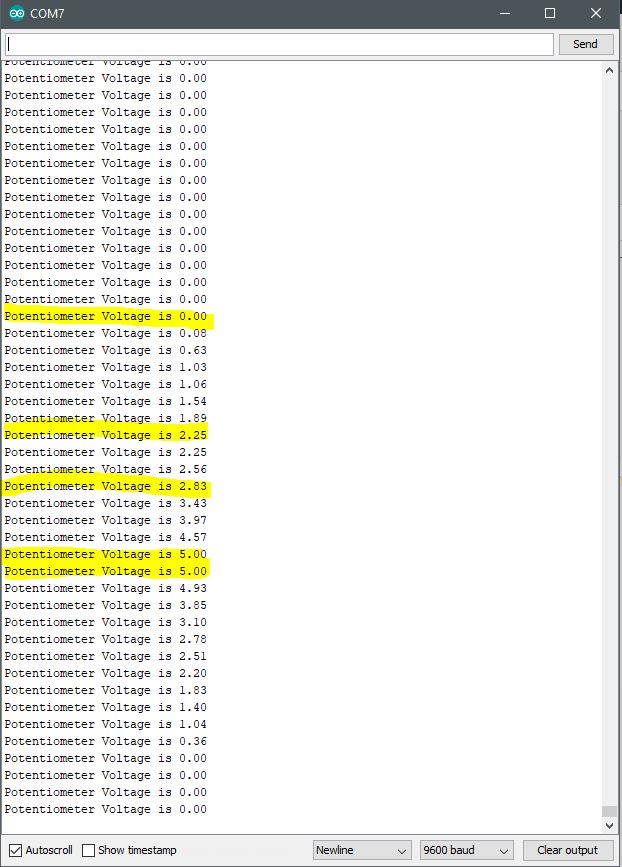
In this case, as the voltage level changes within the 0 to 5VDC scale, the level value is calculated within the Arduino code and displayed out onto the Arduino serial monitor. Moreover, that value is then compared to an argument, such as a maximum or minimum level, to illuminate an LED or turn it off again. The LED simply represents a circuit functions that could otherwise be something else such as a relay, actuator, solenoid, or another analog or digital function.
Hardware Setup:
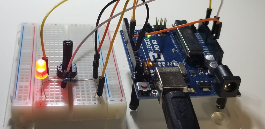
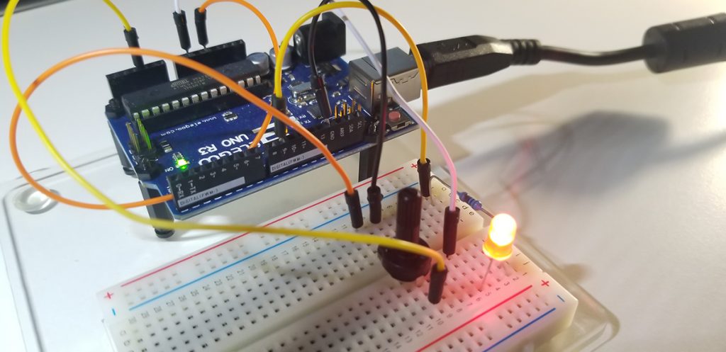
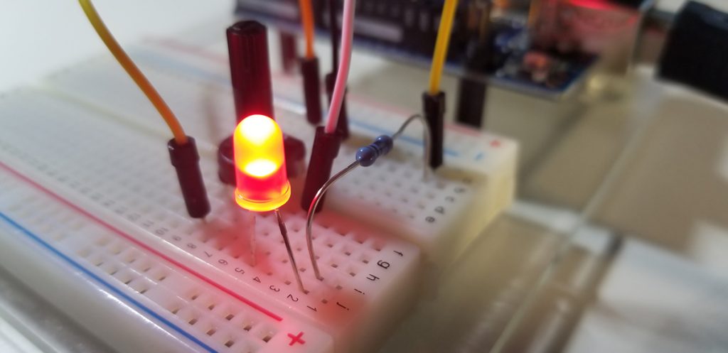
Code Setup:
int myPin=A2;
int readVal;
int redPin=9;
float V2;
int dt=500;
void setup()
{
Serial.begin(9600);
pinMode(myPin,INPUT);
pinMode(redPin,OUTPUT);
}
void loop()
{
readVal=analogRead(myPin);
V2=(5./1023.)*readVal;
Serial.print(“Potentiometer Voltage is “);
Serial.println(V2);
if (V2>2 && V2<3) // && –> Logical AND Operation
{
digitalWrite(redPin,HIGH);
} if (V2<2 || V2>3) // || –> Logical OR Operation
{
digitalWrite(redPin,LOW);
}
delay(dt);
}
The IF statement parameters that serve as an evaluation condition, could be simple less-than, or greater than, logic, equal-to (==), not equal-to (!=), and others by a constant or variable assignment. In this case, V2 is the value in memory that is checked while changes are made at the potentiometer controller to determine if an operating condition is true. Specifically, if the control voltage is between 2 and 3VDC, illuminate the LED. If the voltage is not between 2 and 3VDC, then turn the LED off.
Arduino IDE:
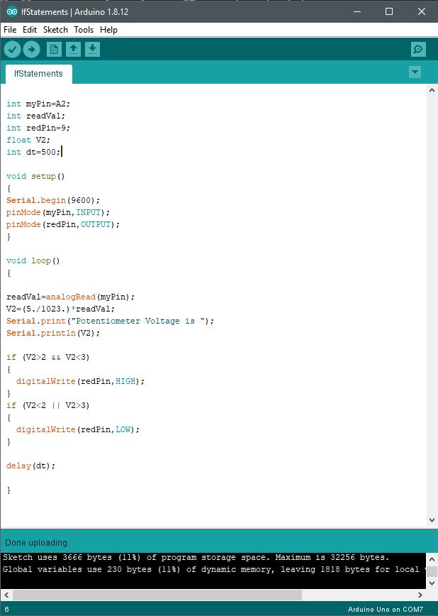
Further Project Details: -Paul McWhorter


Comments are closed.