Tag Archives | arduino

Arduino Clone Bootloader Setup & Programming

Arduino modules (in this case an Arduino Nano 3.0) may come from China without the hardware initialized with a suitable bootloader. Necessary for project work and programming, a bootloader configuration is necessary for an Arduino to connect to a local host computer and its Arduino Sketch IDE. To install a bootloader into the clone Arduino, it is necessary to connect it to a known functional Arduino unit (in this example another Nano) and configure the functional Arduino to set up and configure the bootloader code for the target Arduino clone.

Side by side are the source and target Arduino units to set up and configure the bootloader at the target device (the black Arduino Nano).

Once the bootloader set up and programming is successful, the clone Arduino is prepared for standard project work and programming as desired.

A host computer connects to the source Arduino Nano via USB-Mini male to USB-A male. From there, the source Arduino Nano serves as a host for the target Arduino clone. Bootloader code that resides in the source is transferred to the clone with the connections made and the burn utility within the Arduino IDE.

Programming Method

Step 1 | Configure IDE and Load Arduino ISP

  1. Connect functional Arduino to the USB port on your computer. A USB-Mini male to USB-A male cable is necessary to make this connection. No USB connection is made to the clone Arduino.
  2. Open the Arduino IDE software.
  3. Select the correct COM port available from the Arduino menu (Tools > Port > Serial ports). Choose one COM port such as COM1, COM3, COM5, etc.
  4. Select the correct Arduino board from the Boards Manager menu option (Tools > Board: Arduino Nano (in this example).
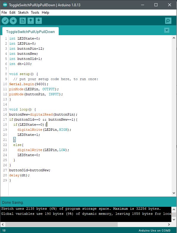
  5. Open Arduino ISP to functional Arduino connected to the host computer via USB mini (Nano) to USB-A (computer). To open the Arduino ISP file select the correct example file (File > Examples > Arduino ISP). Once selected, the Arduino ISP code should open within the Arduino IDE as a Sketch.
  6. Upload the Arduino ISP code to the functional Arduino (Nano in this case).
  7. Unplug the functional Arduino USB cable and complete the six connections to the clone Arduino as described in step 2 below.

If the Arduino ISP code is needed separately (step 5 above), see the download button/link below.

Step 2 | Connect Arduinos

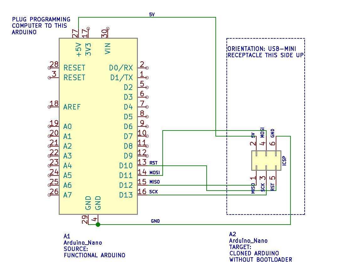
  1. Connect pin 1 on Arduino clone to D12 of functional Arduino.
  2. Connect pin 2 on Arduino clone to 5V of functional Arduino.
  3. Connect pin 3 on Arduino clone to D13 of functional Arduino.
  4. Connect pin 4 on Arduino clone to D11 of functional Arduino.
  5. Connect pin 5 on Arduino clone to D10 of functional Arduino.
  6. Connect pin 6 on Arduino clone to GND of functional Arduino.
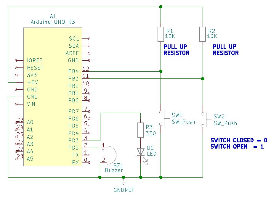
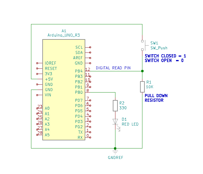
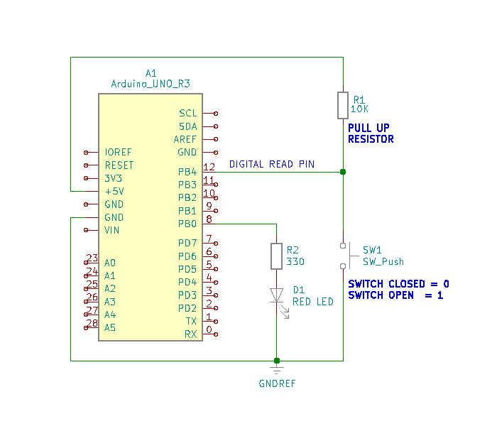
Wiring Schematic

This diagram illustrates how to connect both a functional and clone Arduino together for bootloader programming to the clone. Important: connections D10 – D13 (digital pins 10-13 of the functional Arduino) are the connections to the clone Arduino. For example, do not connect reset or RST of the functional Arduino to the RST of the clone Arduino. Instead, connect D10 of the functional Arduino to pin 5 of the clone Arduino.

Schematic diagram of source and target Arduino units for bootloader upload to a clone Arduino.

Proceed to step 3 below once all connections are made as described in step 2 above, or as illustrated in the wiring schematic above.

Step 3 | Code Load Bootloader

  1. Connect the USB cable to the functional Arduino again for power and programming. This is the same connection made earlier when the Arduino ISP was uploaded to the Arduino unit.
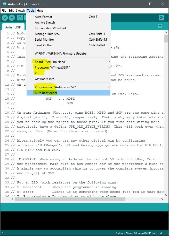
  2. Confirm the correct COM port is selected (Tools > Port > Serial ports). Choose one COM port such as COM1, COM3, COM5, etc.
  3. Select the correct Arduino board from the Boards Manager menu option (Tools > Board: “Arduino Nano” (in this example)).
  4. Select the correct processor from the menu (Tools > Processor > ATmega328P).
  5. Select the correct Arduino programmer from the menu (Tools > Programmer: “Arduino as ISP”)
  6. Select from the Arduino menu the bootloader utility (Tools > Burn Bootloader) to program the target clone Arduino with the bootloader file. Confirm from the Arduino IDE that the upload is completed (observe the “Done” message at the lower IDE window pane). The LEDs on both Arduino units flash during the bootloader programming and stop once the process is done.
Arduino Sketch IDE menu tools for bootloader setup and transfer.

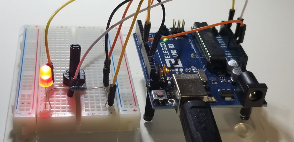
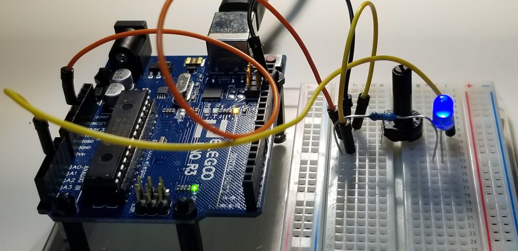
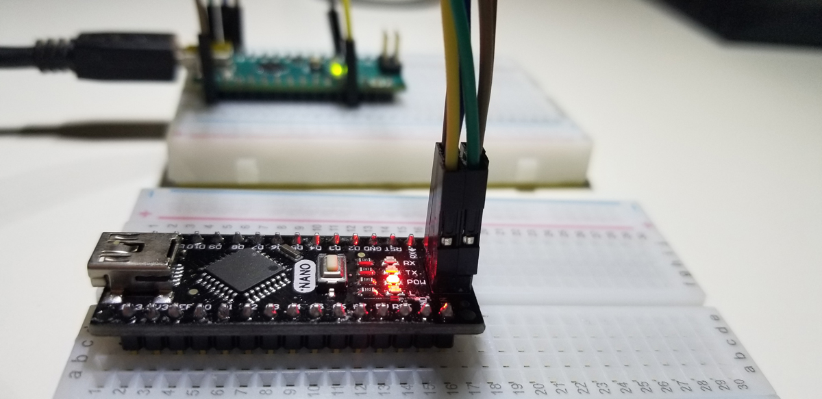
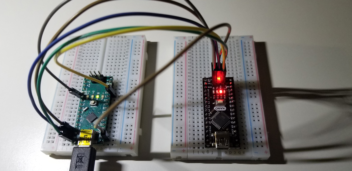
Hardware Demonstration of Bootloader Transfer

This brief video demonstrates the LED activity before, during, and after the bootloader programming. The Arduino Nano on the left is the source and the Arduino Nano clone on the right is the target.


Pushbutton Switch Dimmer Control & Alarm

This project controls an increasing and decreasing voltage level in increments to represent a dimmer present at an LED. An in-circuit buzzer serves as an alarm to indicate either a maximum or minimum level is attained. Two separate pushbutton switches are up / down controls at programmable increments.

Both switches are set up in a common physical configuration only attached to separate GPIO ports. The difference between their operation rests within the code. Brightness increments are defined within the code as is the decrements. Each increment and decrement interval is code-defined as both switches are attached as inputs to separate GPIO ports. The LED is simply an indicator of a GPIO output to show what the increments and decrements are doing (increasing and decreasing voltage levels).
The buzzer that operates as an alarm triggers when the pushbutton switch is pressed too much or too long. As increments increase to a cap (255) or decrease to a floor (0), the alarm will sound to indicate there is no further increase or decrease available. The dimming or brightness levels off and goes no further.

One pull up resistor for each pushbutton switch is necessary to correctly assert each GPIO input to control circuit and code activity. Four total GPIO pins used, each one for its dedicated function. There is no attempt to make dual use of a GPIO port.

Project schematic to illustrate connections and devices interfaced to the Arduino SBC.

Program & Functional Operation:


Code Setup:

int buttonPin1=12;
int buttonPin2=11;
int buzzPin=2;
int LEDPin=3;
int buttonVal1;
int buttonVal2;
int LEDbright=0;
int dt=500;

void setup() {
pinMode(buttonPin1,INPUT);
pinMode(buttonPin2,INPUT);
pinMode(LEDPin,OUTPUT);
pinMode(buzzPin, OUTPUT);
Serial.begin(9600);
}

void loop() {
buttonVal1=digitalRead(buttonPin1);
buttonVal2=digitalRead(buttonPin2);
Serial.print(“Button 1 = “);
Serial.print(buttonVal1);
Serial.print(“, “);
Serial.print(“Button 2 = “);
Serial.println(buttonVal2);
delay(dt);

if (buttonVal1==0){
LEDbright=LEDbright+25;
}
if (buttonVal2==0){
LEDbright=LEDbright-25;
}
Serial.println(LEDbright);
if (LEDbright>255){
LEDbright=255;
digitalWrite(buzzPin,HIGH);
delay(dt);
digitalWrite(buzzPin,LOW);
Serial.println(“Buzz High”);
}
if (LEDbright<0){
LEDbright=0;
digitalWrite(buzzPin,HIGH);
delay(dt);
digitalWrite(buzzPin,LOW);
Serial.println(“Buzz Low”);
}

analogWrite(LEDPin, LEDbright);

}

Arduino Set Up:

Partial view of the code to operate the project. The full code is in the text field above.

Serial display of printed values to indicate states of switch buttons and increment or decrement values of 25. The smaller the increment or decrement, the more pushbutton switch presses are needed to reach either upper or lower limit. Increment and decrement was set arbitrarily in the code to initialize a reasonable value of 25 to reduce the time and clicks it takes to get to the maximum and minimum (0 – 255).

Toggle Switch PullUp with digitalRead

This project involves a toggle switch that an Arduino UNO recognizes through code as necessary to activate an LED over a GPIO pin. Assembly of the circuit requires a 330 resistor, 10K resistor, normally open pushbutton switch, and a red LED plus some jumpers. For added clarity about the assembly refer to the photos below. The schematic illustration merely offers a symbolic representation of the setup. The prior project involved the use of pushbutton switch that temporarily enabled an output (LED) from a GPIO pin.

This project changes the state of the GPIO (LED) each time the pushbutton is pressed. The pushbutton switch in this way operates as a toggle as a steady-state on/off through conditional instruction statements written into the code.

Simple set up of a small circuit to interface with the Arduino UNO R3 SBC. Includes 330 ohm, 10K ohm current limiting resistors, a RED LED, and a small pushbutton normally open switch. Circuit jumpers interface to the Arduino’s GPIO ports.

Top down view of circuit connections.

To register active high and active low states at a GPIO port, it is necessary to apply pull up or pull-down resistors to a circuit’s normally open or normally closed pushbutton switch. It is not an acceptable practice to place a GPIO pin directly to a +5V source, or Ground in order to operate a directly connected switch. The purpose of a pulldown or pullup resistor placed onto a switch is to correctly register an active high or low state at an assigned GPIO measurement pin. To illustrate the connections see the diagrams below:

Pull Up Resistor Example
Pull Down Resistor Example

Simply put, there just must be a circuit path to either a voltage reference or ground reference using a resistor connected to a switch for proper operation. The active voltage present at pin-12, while the button switch is not pressed, is 5VDC. When the pushbutton switch is pressed this voltage level drops to 0VDC. As a 0VDC state is read into pin 12 by the digitalRead operation (i.e. pin 12 becomes grounded), pin 8 presents 5VDC to R2 for the Red LED to illuminate. While the pushbutton switch is pressed and held closed, the serial monitor presents a digital “0” state. This is due to the placement of the digitalRead command within the continuous program loop.

To run the project it is necessary to assemble the circuit onto a breadboard using the components identified above. When the hardware is set up, it is then necessary to write and run the code to get functional use of the project.


Code Setup:

int LEDState=0;
int LEDPin=8;
int buttonPin=12;
int buttonNew;
int buttonOld=1;
int dt=100;

void setup() {
// put your setup code here, to run once:
Serial.begin(9600);
pinMode(LEDPin, OUTPUT);
pinMode(buttonPin, INPUT);
}

void loop() {
buttonNew=digitalRead(buttonPin);
if(buttonOld==0 && buttonNew==1){
if(LEDState==0){
digitalWrite(LEDPin,HIGH);
LEDState=1;
}
else{
digitalWrite(LEDPin,LOW);
LEDState=0;
}
}
buttonOld=buttonNew;
delay(dt);
}

With all suitable integer variables declared, operational instructions become written to perform their intended purpose. Standard pin mode set up declarations are made, and thereafter, the main loop program begins.

The digitalRead operation is executed as the buttonPin command is asserted. The physical state change that occurs from the button switch is detected at the Arduino port (pin 12) and that change is digitally read into memory and stored to the buttonNew variable. Once a switch state is read into memory via the GPIO port, the next set of instructions act upon those states held into memory.

The if-else statement parameters check for the high or low (5VDC or 0VDC) level presented to GPIO pin 12. As the buttonOld and buttonNew variables are checked for true status against assigned states “0” to buttonOld and “1” to buttonNew, the next if-statement is executed. The LEDState is checked for a logic 0 state and if it is true, the digitalWrite command places a HIGH state (logic 1, 5VDC) to the LEDPin (pin 8) GPIO port. The LEDState is then given a logic 1 into its memory space to initialize it for repeat evaluation during the continuous loop in function. Once the true state instructions are executed within both ‘if’ commands, the program falls through the function to bypass the ‘else’ code segment and continues through to the rest to the program until completion where the loop again begins.

The second half of the conditional function, ‘else’ supports the logic evaluation that previously occurred between the buttonNew and buttonOld ‘recognized’ states. If the combination of both variable assessments proves false, the else statement becomes effective within the loop to set the LEDPin to Low. This is the equivalent of a logic evaluation that checks for voltage transitions low to high and turn the LED off. Each time this transition occurs, the program loop writes the active high to turn the LED on or off. The next low-to-high button switch transition evaluation occurs within the ‘else’ segment of the conditional loop to again set the GPIO pin to low (pin-8 LED off) if that else condition should become true.

As the program loop continuously runs, the GPIO pin accepts state changes to operate as a toggle on and off, then on and off again.


Arduino IDE:

Code set up in the Arduino IDE (Sketch).

Arduino Uno Set-Up

As previously posted with the RPi set up, the same is illustrated here but for Arduino Uno. A very common single board computer that is entry level and simple to set up and operate

As before, three areas of interest are given.

Block Diagram
Pin Out Diagram
Tool Chain

The purpose of each work together to build hardware and software controller applications that operate with a host or in a freestanding manner.

While Arduino is widely understood as an entry-level SBC, it can be found among enthusiasts, makers, and project minded people who wish to build projects and code them for unique applications. Centered on the ATMega microcontroller, the software support is deep in a large community of developers. The development environment is an IDE appropriately named Sketch.

Arduino Uno Hook-up Diagram
Continue Reading →

Conditional IF Operation with Logic Parameters

To evaluate the function and purpose of an IF statement, a true or false, or comparative operation is performed for external circuit hardware to act upon conditions or an input of some type. In this case, as a trim potentiometer control is rotated, an output voltage level changes between 0 and 5VDC at an input pin connected to the control. This pin is using an analogRead to get the changing voltage value present at the control within the circuit to perform new functions elsewhere within the Arduino UNO unit.

In this case, as the voltage level changes within the 0 to 5VDC scale, the level value is calculated within the Arduino code and displayed out onto the Arduino serial monitor. Moreover, that value is then compared to an argument, such as a maximum or minimum level, to illuminate an LED or turn it off again. The LED simply represents a circuit functions that could otherwise be something else such as a relay, actuator, solenoid, or another analog or digital function.

Hardware Setup:

Wiring of the potentiometer with LED at two separate GPIO Ports for independent control using Arduino code.
Added setup illustration to indicate connectivity.
LED indicator only illuminate when conditional statements are true. As a test condition, code checks for scaled voltage present at GPIO pin and turns on or off LED accordingly.

Code Setup:

int myPin=A2;
int readVal;
int redPin=9;
float V2;
int dt=500;

void setup()
{
Serial.begin(9600);
pinMode(myPin,INPUT);
pinMode(redPin,OUTPUT);
}

void loop()
{

readVal=analogRead(myPin);
V2=(5./1023.)*readVal;
Serial.print(“Potentiometer Voltage is “);
Serial.println(V2);

if (V2>2 && V2<3) // && –> Logical AND Operation
{
digitalWrite(redPin,HIGH);
} if (V2<2 || V2>3) // || –> Logical OR Operation
{
digitalWrite(redPin,LOW);
}


delay(dt);
}

The IF statement parameters that serve as an evaluation condition, could be simple less-than, or greater than, logic, equal-to (==), not equal-to (!=), and others by a constant or variable assignment. In this case, V2 is the value in memory that is checked while changes are made at the potentiometer controller to determine if an operating condition is true. Specifically, if the control voltage is between 2 and 3VDC, illuminate the LED. If the voltage is not between 2 and 3VDC, then turn the LED off.

Arduino IDE:

Code set up in the Arduino IDE (Sketch).
Continously scrolled voltage values presented as potentiometer wiper is rotated. To demonstrate the voltage scale and range as a function of analogRead operation.

Further Project Details: -Paul McWhorter

Voltage Control with analogRead Operation

With the use of a potentiometer (trim-pot), it is possible to control a voltage level presented to an external circuit from a reference supply voltage connected to an Arduino unit. Through the use of a trim-pot, a supply voltage scales up or down between 0V and the supply voltage (5VDC) by continuous rotation of its control shaft or wiper.

The three pins or leads of a potentiometer are connection points to a supply or circuit elements for purposes of voltage and signal control. Two outer leads are each end of the potentiometer’s total resistive element. The center pin serves as a connection for a wiper that internally travels between each outer point. As a potentiometer shaft or wiper is rotated, the resistance at the center point provides for a change in voltage level at that wiper connection. Where the resistance is the total between two points as given by the symbolic illustration below. Connections made between pins 1 and 2 or pins 2 and 3 are therefore always lower in resistance than connections made between pins 1 and 3. As the wiper shaft is rotated between pins 1 and 3, the resistance, therefore, changes between either of the two pins 1 or 3. So any voltage present across either pair of pins will become scaled to either the highest or lowest voltage. Since according to ohm’s law, resistance is directly proportional to voltage, the higher the resistance between two pins, the greater the voltage becomes present between those two points.

As a side matter of interest, it is necessary to recognize that the taper of the potentiometer affects the rate by which resistance or voltage changes as a wiper control is rotated. So, both linear or log continuously variable potentiometers or trim-pots are available to affect the rate in which control changes can occur. Potentiometers are also at times detented or non-detented depending upon what is selected. Detented pots are clicked into each rotated position as a control wiper is moved from one position to the next as it is rotated. More information about the theory and operation of potentiometers can be found here.

Schematic Symbol of Potentiometer
3D Rendering of Trim Pot Potentiometer

A demonstration of voltage control is demonstrated in the video below. As the wiper is rotated, the voltage level presented at the center pin of the trim pot is changed within the limits of 0VDC to the maximum voltage (5VDC). In this instance, an LED is connected to the wiper pin and its illumination level is increased or decreased as a function of voltage level.


To build the circuit and operate the control, simple connections are made between an Arduino UNO and its external components as depicted below. The purpose of the Arduino is to provide the source voltage and connections for voltage level readout using the analogRead command.

Hardware Setup:

Simple Connectivity of LED to Potentiometer / Trim Pot
Circuit Set Up of Arduino and Trim Pot for Voltage Readout and LED Illumination

The code set up involves the configuration as written about previously in a prior post. The setups involve the three areas of interest to include variable declarations by datatype, system communication rate (9600 BAUD) between a host computer, and the Arduino’s serial monitor via the Sketch IDE. Finally, the operating code provides the instructions and commands by which operations are performed.

Code Setup:

int myVoltPin=A2;
int readVal;
float V2;
int delayT=250;

void setup()
{
Serial.begin(9600);
}

void loop()
{
readVal=analogRead(myVoltPin);
V2=(5./1023.)*readVal;
Serial.println(V2);
delay(delayT);
}

Arduino IDE:

Code set up in the Arduino IDE (Sketch).
Continuously scrolled voltage values presented as potentiometer wiper is rotated. To demonstrate the voltage scale and range as a function of analogRead operation.

Further Project Details: -Paul McWhorter

Voltage Measurement by analogRead Operation

A useful way of reading a voltage signal level is through an Analog Input port on the Arduino. With accompanied code to collect, interpret, calculate, display, and act upon a static of dynamic voltages from a circuit, discrete numerical values are presented to a user. In this project, those values are displayed via the Arduino Sketch Serial Monitor. As necessary to bring those values together, in an effort to read an actual voltage, it is necessary to build a circuit or tap an existing circuit, and write the code to get the readings desired. In this case, it is important to also perform a conversion of read values from binary equivalent numbers due to the Arduino UNO in this project that uses a 10-bin A/D converter (210 – 10-bit resolution or 1024 distinct values for a single point of measurement).

There are numerous basic applications from this function as a separate or partitioned segment of capability that pertains to other relevant purposes. The reason it is so important to understand this capability is because of its relevance as a fundamental building block elsewhere. Just as there are many other building blocks, this is a key capability that has a bearing on how projects come together using both a combination of hardware and software.

This code includes variables to initialize conditions by which the entire program operates. These variables must be declared using a data type that specifies how they are acted upon. In this example, integer and float data types get declared to establish precision for accuracy and proper computations or handling. Afterward, the program involves set up commands to configure the program and operate functions as intended. Finally, the void loop() function provides for the instructions to execute programmatically.

In this example, under the void loop(), the physical voltage read into the analog port is the value presented to the analog-to-digital converter. As this value is stored into variable memory readVal, it is multiplied by a coefficient (5./1023.). This calculation becomes necessary as the numerical value read into the readVal memory isn’t a voltage level as given by a meter. So, the calculation of 5VDC ÷ 1023 values gives a ratio of two maximum values as represented as voltage (numerator) and resolution (denominator). This calculation normalizes the digital value read at the analog port input to a voltage value read into memory (V2) or displayed as desired. V2, in turn, is read out at the serial monitor utility from the Arduino Sketch IDE to make tangible the entire operation. Meaning, a readout of voltage using an Arduino module and a host computer instead of a separate dedicated meter.

// declare variables
int readPin=A3;
int readVal;
float V2=0;
int delayTime=500;

void setup() {
// put setup code here, to run once while using any relevant variable declared above

pinMode(readPin,INPUT);
Serial.begin(9600);
}

void loop() {
// put main code here, to run repeatedly. runs in a continuous loop until interrupted or physically halted

readVal=analogRead(readPin);
V2=(5./1023.)*readVal;
Serial.println(V2);
delay(delayTime);

}

Stable Circuit Operating Voltage
Port Connections. Reference Voltage & Analog Input Voltage
Simple Voltage Divider Circuit (330Ω & 100Ω)
Code Implementation of Voltage Meter
Selected Voltage Value for Arduino AnalogRead
Serial Monitor Value Reading from Arduino AnalogRead

Further Project Details: -Paul McWhorter

Pulse Width Modulated (PWM) LED Illumination

To get a closer look at the analogWrite command supported by the Arduino platform, its internal pulse width modulation (PWM) function controls the duty cycle of an output voltage to drive an external circuit. More basically, you can assign argument values to the analogWrite command to affect a change in signal to an outside circuit. This is where the is a possibility of setting a discrete or continuously incremented or decremented values. Where a corresponding level is brightness intensity is observed.

int redPin=9;
int bright=127; // 0 = 0V 255 = 5VDC

void setup()
{
pinMode(redPin,OUTPUT);
}

void loop()
{
analogWrite(redPin,bright);
}

The output scale of 0 to 255 represents 256 unique values (28 = 256). Where 2 represents the two binary states 0 and 1 store in 8-bits of addressable data for registers to execute or process instructions in support 256 separate and unique values in RAM or ROM memory storage. In this case, the values selected along the scale between 0 to 255 provide increasing values of analog to digital conversion that eventually represent a full-scale value of an output voltage as a function of the available supply given to the controller.


Hardware Set Up:

Notice that the pin identifiers at each suitable port with the ” ~ ” indicator supports PWM analog functionality. This is in contrast with the digitalWrite pins without the ” ~ ” symbol that does not support analog read/write operation. 

PWM Waveform Explanation:

As depicted in this diagram, the waveform is at about a 50% duty cycle with an analogWrite argument value set to 127. Peak value is at 4.960V in the measurement as indicated by the cursor, but the illumination intensity is significantly lower than full brightness because the area under each pulse is reduced by about 50% or half. The cursor and statistics data in the screen capture gives the details about the change in behavior as compared to a 255 analogWrite argument value. In such a case, the waveform would appear as a straight line on an oscilloscope for 100% of available brightness. That is full available power presented to an output circuit, which in this case is an LED. 

Arduino IDE:

The simple code set up within the Arduino Sketch IDE to show the details of the operation. 

Further Project Details: -Paul McWhorter

LED Blink Illumination in Sequential Morse Code

This project involves a simple circuit that involves three LEDs that illuminate in succession to indicate the presence of an SOS signal in Morse Code. The physical set up of the physical set up involves a red, green, and blue LED connected to three separate ports on an Arduino Uno. All share the same ground path and are current-limited by separate 330-ohm resistors. We have here a hardware set up of code to support a (dot, dot, dot, dash, dash, dash, dot, dot, dot) repeating pattern of illumination as a visual indication of messaging (••• – – – •••).

Each dot is a shorter on/off period of time as compared to a longer period for a sequence of three dashes. Following another three dots until the cycle repeats itself after a short delay.


Arduino IDE:

Arduino Code:

int redLED=8;
int greenLED=9;
int blueLED=10;

float pi=3.14;
int dit=100;
int dah=500;
int LongW=2000;

String myName=”[Place Holder]”;

void setup() {
// put setup code here, to run once:
pinMode(redLED,OUTPUT);
}

void loop() {
// put main code here, to run repeatedly:

digitalWrite(redLED,HIGH);
delay(dit);
digitalWrite(redLED,LOW);
delay(dit);

digitalWrite(redLED,HIGH);
delay(dit);
digitalWrite(redLED,LOW);
delay(dit);

digitalWrite(redLED,HIGH);
delay(dit);
digitalWrite(redLED,LOW);
delay(dit);

digitalWrite(greenLED,HIGH);
delay(dit);
digitalWrite(greenLED,LOW);
delay(dit);

digitalWrite(greenLED,HIGH);
delay(dit);
digitalWrite(greenLED,LOW);
delay(dit);

digitalWrite(greenLED,HIGH);
delay(dit);
digitalWrite(greenLED,LOW);
delay(dit);

digitalWrite(blueLED,HIGH);
delay(dit);
digitalWrite(blueLED,LOW);
delay(dit);

digitalWrite(blueLED,HIGH);
delay(dit);
digitalWrite(blueLED,LOW);
delay(dit);

digitalWrite(blueLED,HIGH);
delay(dit);
digitalWrite(blueLED,LOW);
delay(dit);

digitalWrite(redLED,HIGH);
delay(dah);
digitalWrite(redLED,LOW);
delay(dah);

digitalWrite(redLED,HIGH);
delay(dah);
digitalWrite(redLED,LOW);
delay(dah);

digitalWrite(redLED,HIGH);
delay(dah);
digitalWrite(redLED,LOW);
delay(dah);

digitalWrite(greenLED,HIGH);
delay(dah);
digitalWrite(greenLED,LOW);
delay(dah);

digitalWrite(greenLED,HIGH);
delay(dah);
digitalWrite(greenLED,LOW);
delay(dah);

digitalWrite(greenLED,HIGH);
delay(dah);
digitalWrite(greenLED,LOW);
delay(dah);

digitalWrite(blueLED,HIGH);
delay(dah);
digitalWrite(blueLED,LOW);
delay(dah);

digitalWrite(blueLED,HIGH);
delay(dah);
digitalWrite(blueLED,LOW);
delay(dah);

digitalWrite(blueLED,HIGH);
delay(dah);
digitalWrite(blueLED,LOW);
delay(dah);

digitalWrite(redLED,HIGH);
delay(dit);
digitalWrite(redLED,LOW);
delay(dit);

digitalWrite(redLED,HIGH);
delay(dit);
digitalWrite(redLED,LOW);
delay(dit);

digitalWrite(redLED,HIGH);
delay(dit);
digitalWrite(redLED,LOW);
delay(dit);

digitalWrite(greenLED,HIGH);
delay(dit);
digitalWrite(greenLED,LOW);
delay(dit);

digitalWrite(greenLED,HIGH);
delay(dit);
digitalWrite(greenLED,LOW);
delay(dit);

digitalWrite(greenLED,HIGH);
delay(dit);
digitalWrite(greenLED,LOW);
delay(dit);

digitalWrite(blueLED,HIGH);
delay(dit);
digitalWrite(blueLED,LOW);
delay(dit);

digitalWrite(blueLED,HIGH);
delay(dit);
digitalWrite(blueLED,LOW);
delay(dit);

digitalWrite(blueLED,HIGH);
delay(dit);
digitalWrite(blueLED,LOW);
delay(dit);

delay(LongW);

}

Further Project Details: -Paul McWhorter

Frequency Selectability Experiment with Arduino

Here is a short effort to program the control of crystal frequency output. 8MHz as the standing frequency with multipliers asserted one at a time.

This is an experiment to encode in binary a selectable output pulse rate from a 555 timer. Where selected GPIO pins become asserted to set the desired rate. Over an Uno connection with code, I set up a user interface to push millions of pulses through to a defined output. All in a single second each instance. Staring from a single pulse rate with multipliers of 16, 20, 32, and 40. Each one separately is chosen by simply entering what a user wants over a GUI interface.


LED Illumination Control with Arduino Uno

There was an online guide that walks a viewer through how to assign color variable values in code to red, green and blue. To combine each as having relative color strength to produce a mixed color output on an RGB LED. This is a way to prepare unique light color values beyond the conventional LED lights with fixed colors. In this small project, color is programmed within the Arduino IDE and thereafter code loaded into the SBC itself to run the unique color mix.

The code to set up this functionality is set up on Arduino Sketch. To write and edit instructions that determine the operability and behavioral properties of the hardware and circuit.

After declarations and set up, this is what the code looks like.

void loop()
{
Serial.println(“Please input your color choice (red, green or blue): “);
while (Serial.available()==0) {

colorChoice= Serial.readString();

if (colorChoice==”red”)
{analogWrite(redPin,brightness);
analogWrite(bluePin,0);
analogWrite(greenPin,0);
}
if (colorChoice==”green”){
analogWrite(redPin,0);
analogWrite(bluePin,0);
analogWrite(greenPin,brightness);
}
if (colorChoice==”blue”){
analogWrite(redPin,0);
analogWrite(bluePin,brightness);
analogWrite(greenPin,0);
}
if ( colorChoice != “red” && colorChoice != “green” && colorChoice != “blue”) { //test for valid input
Serial.println(“”);
Serial.println(“You have not entered a valid color, please enter red, blue or green”);
Serial.println(“”);
}
}