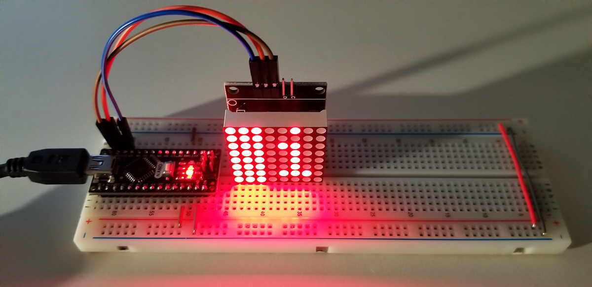
The LED Matrix display in this project can be more versatile than other typical LED indicators. Standard LEDs and 7-segment LEDs have their unique or dedicated purpose for readout or illumination to indicate activity or an event, but this matrix display offers variable messaging capabilities. From within the code driving this display, either visual characters or images are display in a sequential fashion to convey messages.
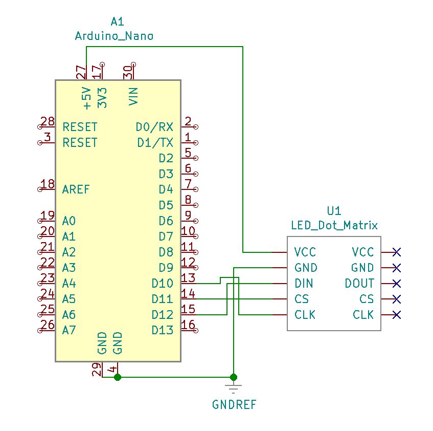
Set up is easy with only three terminations between both the display and the Arduino Nano/Uno. Aside from VCC and ground, CLK (clock), CS (chip-select), and DIN (data-input) are terminated to GPIO pins D12 through D10 respectively. As illustrated in the schematic below the connections are defined for clarity.
Project Schematic:

Project Review:
Running the project is straight-forward with each dot of light representing a single LED element. When combined together, or as a sequence, the display acts as pixels do on a monitory to form characters and images. Only on this display with a higher intensity of light.
Code Example:
#include <LedControl.h>
/* Need a LedControl to work with.
pin 12 is connected to the DIN (data input)
pin 11 is connected to CS
pin 10 is connected to the CLK */
LedControl lc=LedControl(12,10,11,1);
/* Always wait a bit between updates of the display */
unsigned long delaytime1=500;
unsigned long delaytime2=5;
void setup()
{
/* The MAX72XX is in power-saving mode on startup,
it is necessary to wake up the display */
lc.shutdown(0,false);
/* Set the brightness to a medium values */
lc.setIntensity(0,8);
/* Clear the display */
lc.clearDisplay(0);
}
/* This method will display the characters for the word “Arduino” one after the other on the matrix (you need at least 5×7 LEDs to see the whole chars). */
void writeArduinoOnMatrix()
{
/* here is the data for the characters */
byte a[5]={B01111110,B10001000,B10001000,B10001000,B01111110};
byte r[5]={B00010000,B00100000,B00100000,B00010000,B00111110};
byte d[5]={B11111110,B00010010,B00100010,B00100010,B00011100};
byte u[5]={B00111110,B00000100,B00000010,B00000010,B00111100};
byte i[5]={B00000000,B00000010,B10111110,B00100010,B00000000};
byte n[5]={B00011110,B00100000,B00100000,B00010000,B00111110};
byte o[5]={B00011100,B00100010,B00100010,B00100010,B00011100};
/* now display them one by one with a small delay */
lc.setRow(0,0,a[0]);
lc.setRow(0,1,a[1]);
lc.setRow(0,2,a[2]);
lc.setRow(0,3,a[3]);
lc.setRow(0,4,a[4]);
delay(delaytime1);
lc.setRow(0,0,r[0]);
lc.setRow(0,1,r[1]);
lc.setRow(0,2,r[2]);
lc.setRow(0,3,r[3]);
lc.setRow(0,4,r[4]);
delay(delaytime1);
lc.setRow(0,0,d[0]);
lc.setRow(0,1,d[1]);
lc.setRow(0,2,d[2]);
lc.setRow(0,3,d[3]);
lc.setRow(0,4,d[4]);
delay(delaytime1);
lc.setRow(0,0,u[0]);
lc.setRow(0,1,u[1]);
lc.setRow(0,2,u[2]);
lc.setRow(0,3,u[3]);
lc.setRow(0,4,u[4]);
delay(delaytime1);
lc.setRow(0,0,i[0]);
lc.setRow(0,1,i[1]);
lc.setRow(0,2,i[2]);
lc.setRow(0,3,i[3]);
lc.setRow(0,4,i[4]);
delay(delaytime1);
lc.setRow(0,0,n[0]);
lc.setRow(0,1,n[1]);
lc.setRow(0,2,n[2]);
lc.setRow(0,3,n[3]);
lc.setRow(0,4,n[4]);
delay(delaytime1);
lc.setRow(0,0,o[0]);
lc.setRow(0,1,o[1]);
lc.setRow(0,2,o[2]);
lc.setRow(0,3,o[3]);
lc.setRow(0,4,o[4]);
delay(delaytime1);
lc.setRow(0,0,0);
lc.setRow(0,1,0);
lc.setRow(0,2,0);
lc.setRow(0,3,0);
lc.setRow(0,4,0);
delay(delaytime1);
}
/* This function lights up some LEDs in a row.
The pattern will be repeated on every row.
The pattern will blink along with the row-number.
row number 4 (index==3) will blink 4 times etc. */
void rows() {
for(int row=0;row<8;row++) {
delay(delaytime2);
lc.setRow(0,row,B10100000);
delay(delaytime2);
lc.setRow(0,row,(byte)0);
for(int i=0;i<row;i++) {
delay(delaytime2);
lc.setRow(0,row,B10100000);
delay(delaytime2);
lc.setRow(0,row,(byte)0);
}
}
}
/*This function lights up some LEDs in a column.
The pattern will be repeated in every column.
The pattern will blink along with the column-number.
column number 4 (index==3) will blink 4 times etc. */
void columns() {
for(int col=0;col<8;col++) {
delay(delaytime2);
lc.setColumn(0,col,B10100000);
delay(delaytime2);
lc.setColumn(0,col,(byte)0);
for(int i=0;i<col;i++) {
delay(delaytime2);
lc.setColumn(0,col,B10100000);
delay(delaytime2);
lc.setColumn(0,col,(byte)0);
}
}
}
/* This function will light up every Led on the matrix.
The led will blink along with the row-number.
row number 4 (index==3) will blink 4 times etc. */
void single() {
for(int row=0;row<8;row++) {
for(int col=0;col<8;col++) {
delay(delaytime2);
lc.setLed(0,row,col,true);
delay(delaytime2);
for(int i=0;i<col;i++) {
lc.setLed(0,row,col,false);
delay(delaytime2);
lc.setLed(0,row,col,true);
delay(delaytime2);
}
}
}
}
void loop() {
writeArduinoOnMatrix();
rows();
columns();
single();
}


Comments are closed.