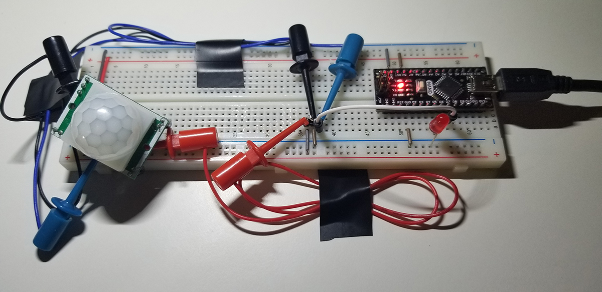
This project involves a motion detector that “observes” its immediate environment to inform the Arduino that an active state change is present. The Arduino in turn processes that state change for code-driven events to make the motion detector a useful device that monitor’s the physical movement of objects in its immediate environment.
The HC-SR501 passive infrared sensor in this project is not an obvious type of sensor to understand in a traditional sense. It consists of active and passive components that facilitate sensitivity and trigger functions that are helpful in its implementation. Two onboard trim pots are adjustment settings that help make the sensor more user friendly. The first concerns the sensor’s distance sensitivity and the second for a time delay after each motion event is triggered.
Further information concerning the sensor with this example is more completely covered in this document.
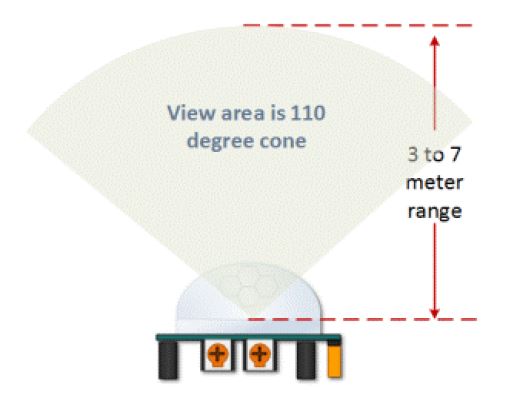
The sensor dome lens in this image helps to support its 110° conical range of view. From the base of the sensor extending out between 3 to 7 meters, according to its adjusted sensitivity, motion detection is limited within this viewing area.
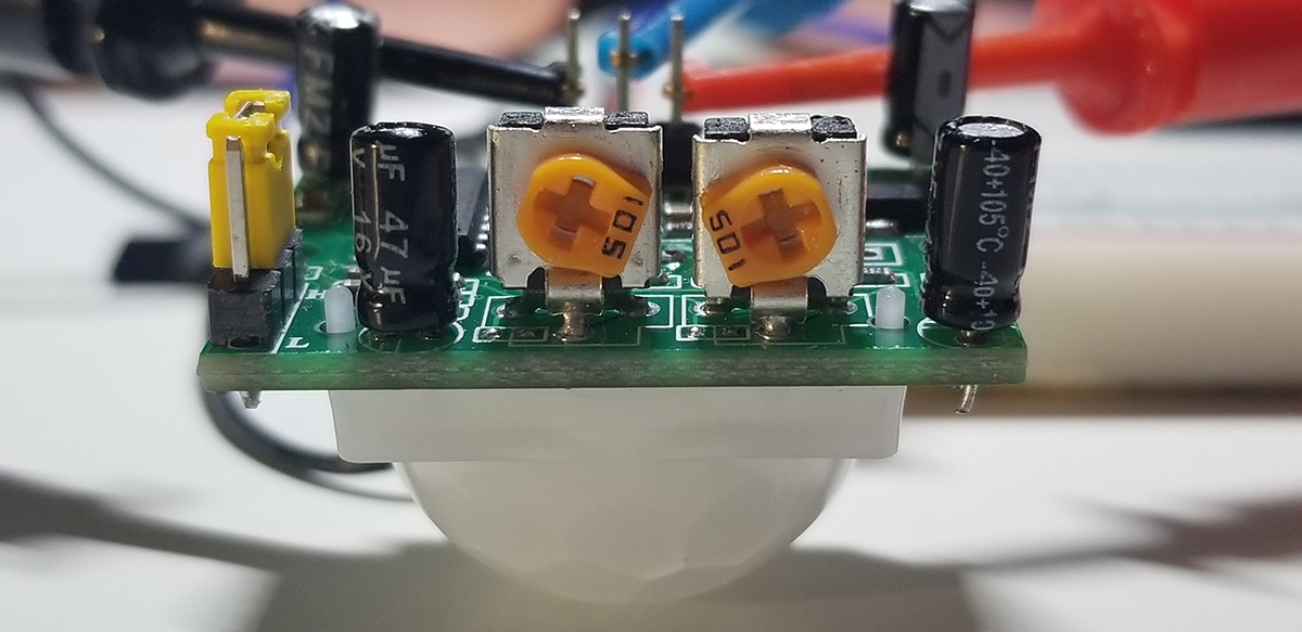
The Passive Infrared Sensor (PIR) detects motion from within its viewing range by the user settings on the HC-SR501 device itself. Two trim potentiometer adjustments with jumper positions as depicted and explained below set the sensor’s interpretation capabilities as defined.
Upon startup, the PIR device requires about 1-minute to initialize. Since the device will output false detection signals, it is necessary to assure associated readings within interfacing circuit logic takes this condition into account.
The viewing area range, as indicated below, is adjustable with two side-by-side trim pots. The sensitivity trim adjustment on the right of the photo above rotates clockwise or counter-clockwise. Fully clockwise sets the sensor’s viewing range to about 3-meters. Fully counter-clockwise sets the sensor’s viewing range to about 7-meters. Variability between these two settings provide for a distance calibration to support an optimum use-case viewing distance.
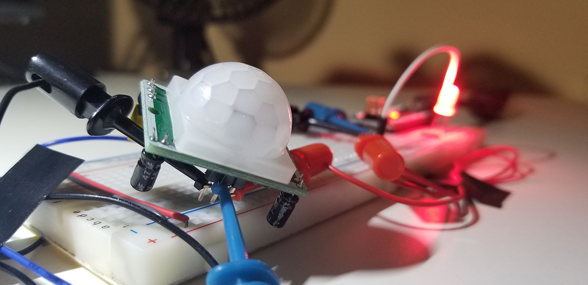
During evaluation or experimentation, it is useful to orient the sensors to suitable positions where detection possibilities are assured. The HC-SR501 doesn’t provide for a suitable, or easy mounting solution to a vector or perforated board unless small standoffs are added to each side of the sensor through the PCB mounting holes (about 1.9 – 2.0mm I.D.).
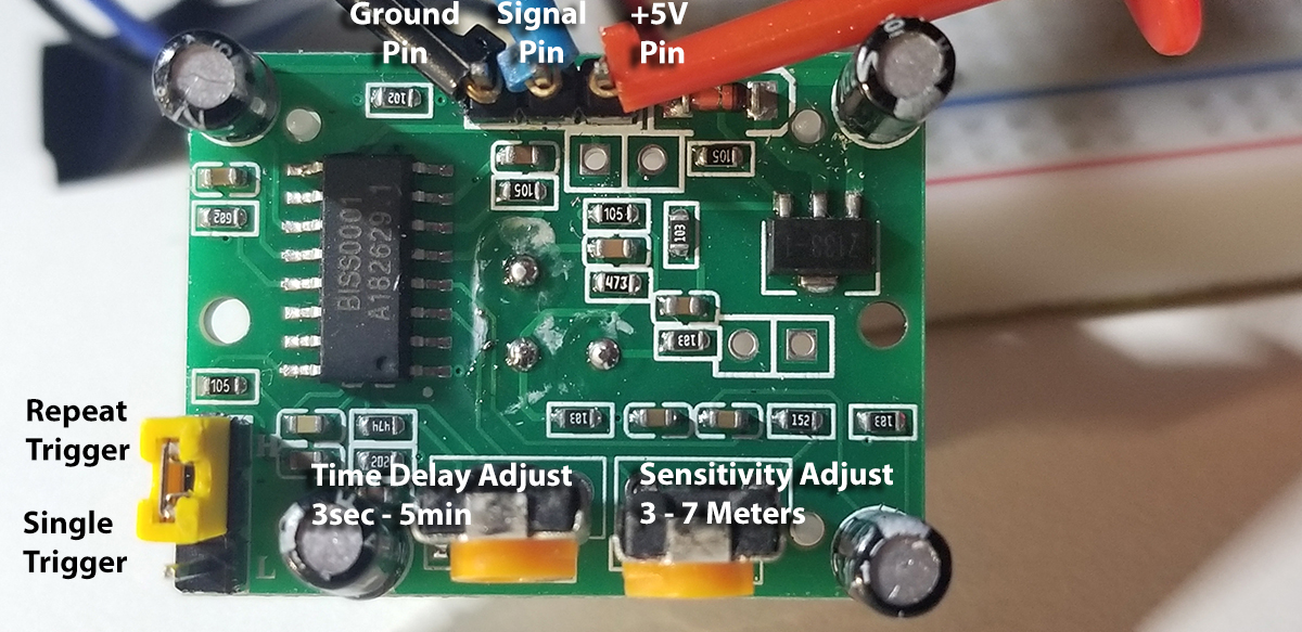
The trim adjustment on the left in the photo above provides for a clockwise and counter-clockwise rotation as well. Fully clockwise increases the delay between detection events to about 5-minutes. Fully counter-clockwise sets the delay to about 3-seconds. This delay occurs after each detection event. It is after each motion detection occurrence that this device signal will go LOW until the set delay is completed. During this delay time, each new detection within the sensor’s viewing range is blocked. Once the delay is completed, any detected motion sets the device output to HIGH. The same delay and detection cycle repeats with these intervals as defined by the sensitivity and viewing range adjustment settings.
The HC-SR501 PIR sensor has three output pins VCC, Output and Ground. It has a DC voltage regulator that accepts 4.5 to 12 volts, so a 5V source is common. The BISS0001 IC is a signal processing chip while diode in the upper left of the photo above is for excess voltage projection. The remaining components are passive resistors and capacitors.
- Time Delay Adjust: This sets how long the output remains high after detecting motion. Anywhere from about 5 seconds to 5 minutes.
- Sensitivity Adjust: Sets the detection range of motion from about 3 meters to 7 meters.
- Trigger Selection Jumper: Set for Single or Repeat trigger events.
- Ground Pin: Input connection for ground reference.
- Output Pin: LOW (0V) when no motion is detected and HIGH (3.3V) when motion is detected.
- VCC Pin: 5VDC to 12VDC input.
The lens cap of the motion detector is easily removable to reveal the PIR sensor mounted to its PCB. The small plastic guideposts are inserted into the PCB to also reveal that the lens cap is detachable. The pinout references for the connector header below are named on the top side of the PCB assembly.
As there are three connection terminals (5V, Ground, and Output), it is also possible to run the sensor freestanding on its own. With 4x AA batteries, a 220 resistor, and an LED, the module operates as a portable yet simple detector for placement just about anywhere practical. For example, a completed assembly in this way can be set in another room where the LED is in viewing distance (or by mirror/camera placement), where it becomes possible to get a primitive notification that someone has entered into that room without you being there.
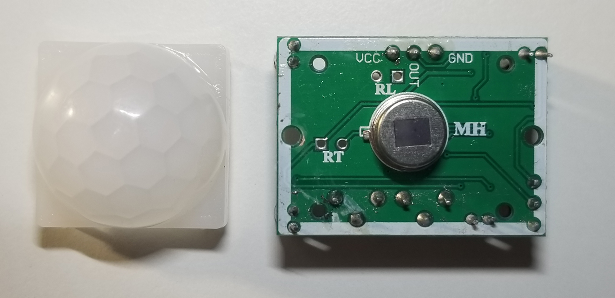
RT– This is for a thermistor or temperature-sensitive resistor. Adding this allows the HC-SR501 to be used in extreme temperatures, it also increases the accuracy of the detector to some degree. RL– This connection is for a Light Dependent Resistor (LDR) or Photoresistor. By adding this component the HC-SR501 will only operate in darkness, a common application for motion-sensitive lighting systems. The additional components can be soldered directly to the board or extended to remote locations using wires and connectors.
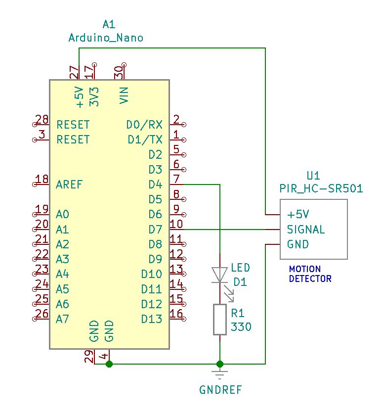
Project Schematic:
The operating voltage of the HC-SR501 is between 5VDC and 12VDC, but in this example using the Arduino Nano it is supply with the same 5VDC source. The LED (D1) is the signal light to indicate when the senor has detected motion.
Project Review:
This motion detection experiment checks for illumination activity as movement is placed before the sensor and just out of range. Additional movement tests are performed while the sensor is in the block state for the duration set by the timing adjustment at the trim potentiometer on the module. The reset of the sensor (and LED) activity is made evident with the jumper setting as described above.
Code Example 1:
This code simply illuminates the LED when motion is detected.
int ledPin = 4; // LED on pin 4 of Arduino
int pirPin = 7; // HC-S501 sensor input to Arduino
int pirValue; // Variable to read PIR Value
void setup()
{
pinMode(ledPin, OUTPUT);
pinMode(pirPin, INPUT);
digitalWrite(ledPin, LOW);
}
void loop()
{
pirValue = digitalRead(pirPin);
digitalWrite(ledPin, pirValue);
}
Code Example 2:
This code illuminates the LED and sends a message to the serial monitor when motion is detected.
int ledPin = 4; // choose the pin for the LED
int inputPin = 7; // choose the input pin (for PIR sensor)
int pirState = LOW; // we start, assuming no motion detected
int val = 0; // variable for reading the pin status
void setup()
{
pinMode(ledPin, OUTPUT); // declare LED as output
pinMode(inputPin, INPUT); // declare sensor as input
Serial.begin(9600);
}
void loop()
{
val = digitalRead(inputPin); // read input value
if (val == HIGH) // check if the input is HIGH
{
digitalWrite(ledPin, HIGH); // turn LED ON
if (pirState == LOW)
{
Serial.println(“Motion Detected!”); // print on output change
pirState = HIGH;
}
}
else
{
digitalWrite(ledPin, LOW); // turn LED OFF
if (pirState == HIGH)
{
Serial.println(“Motion Detected!”); // print on output change
pirState = LOW;
}
}
}


Comments are closed.