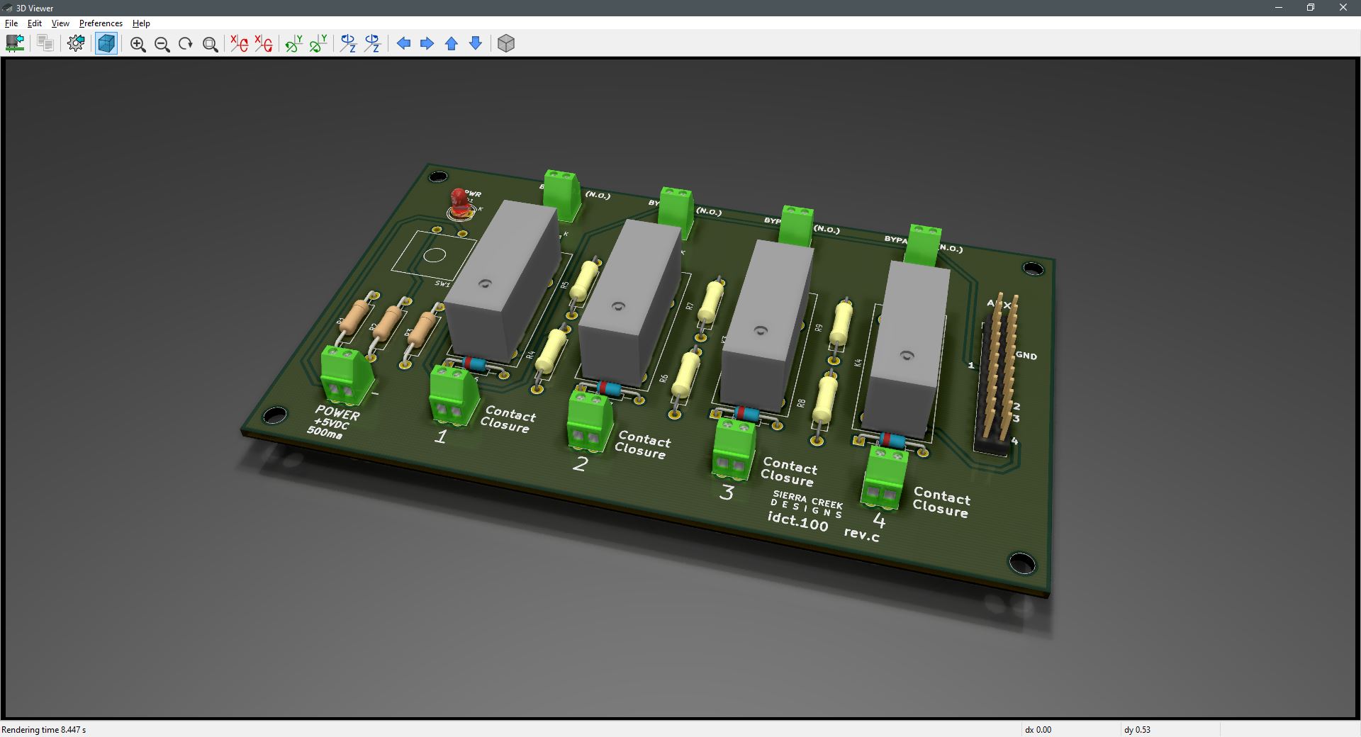
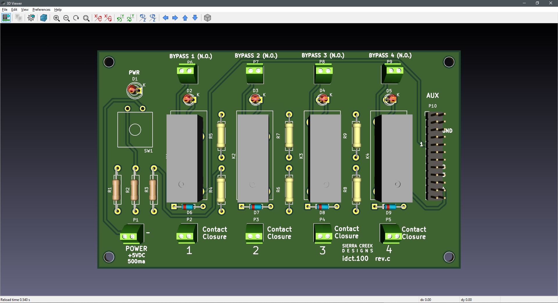
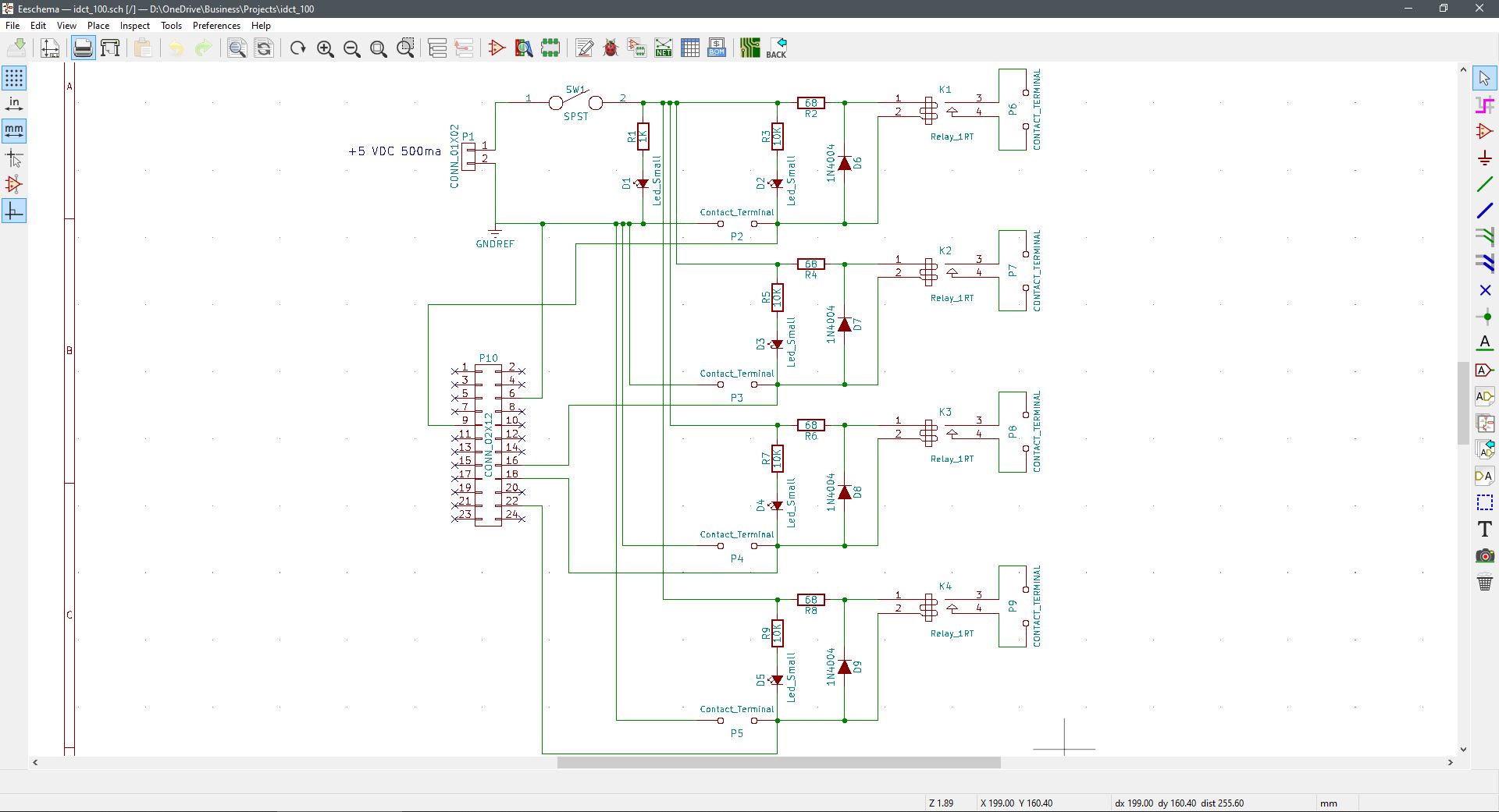
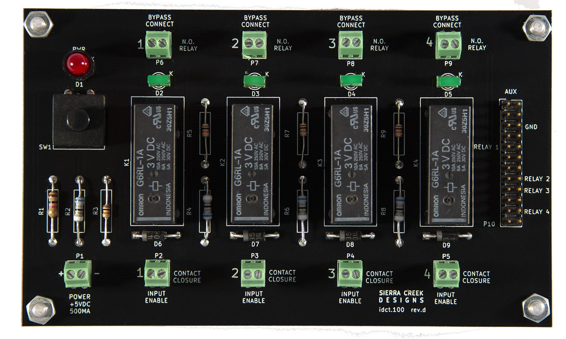
In an effort to combine multiple relays onto a single module, this project accepts a single power supply (PSU). The PSU attached at the P1 terminal block provides power to all relays and associated LED indicators. The LEDs are in place to indicate the active or inactive state of each separate relay. All relays and indicators are aligned in parallel for ease of visual recognition and separation.
All changes have their dedicated input and output terminal blocks. To give an intuitive sense of what hook up terminations are necessary to operate the module. The inputs are labeled as Contact Closure to indicate a functional purpose of each connection. By applying a physical wire connection between each pin at P2, P3, P4, and P5, each relay becomes activated whereby connectors P6, P7, P8, and P9 close. As the pins at these output connectors become closed as a bypass, or completed path. All relays are normally open type components.
The terminal block is another connection point in parallel with contact closure connectors 1 – 4. Only this connector is a pin-header to support an external computer-controlled activation mechanism.


Comments are closed.