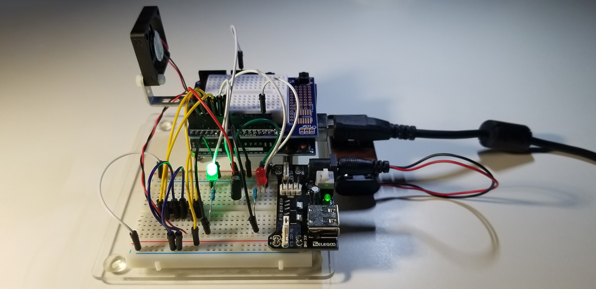
This project was about making a tilt sense system that involves a motor or fan. The system is also programmed and set up with a tip sense light. It simulates a tip-over or roll-over situation and when the system reaches a 90-degree angle from level. At 90 degrees, the sensor drive signal shuts everything down through the Nano. It also has industrial applications as there are different tilt switches at different angles.

Project Schematic:

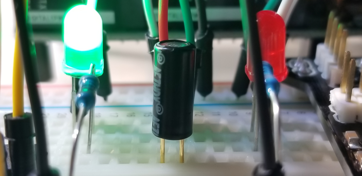
A tilt switch is really just a type of motion sensor that activates after a certain angle from a reference point is reached. Among various approaches toward level detection and sensor motion, this project uses a canister tilt switch that uses a small internal ball that interrupts a closed switch path as it is rolled from one position to another at the component’s specified angle.
At the specified angle, the tilt switch path is open and no further connection between its leads is permitted. For example, in a level state, a tilt device’s upright position settles an internal miniature metal ball for a closed switch path (or “on” function). Conversely, when the position tips beyond its specified angle, the internal metal ball moves to another position where the connection path between the two switch leads become interrupted (or “off” function).
Project Operation:
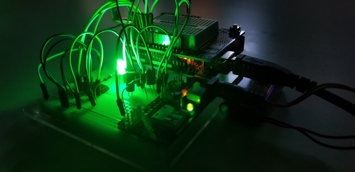
The demonstration of this system zooms in on the states of LED illumination and fan movement as its position changes from level (0-degrees) to upright (90-degrees).
Code Setup:
int speedPin=5;
int dir1=4;
int dir2=3;
int mSpeed=255;
int tiltPin=2;
int tiltVal;
int redPin=7;
int greenPin=6;
void setup() {
Serial.begin(9600);
pinMode(speedPin,OUTPUT);
pinMode(dir1,OUTPUT);
pinMode(dir2,OUTPUT);
pinMode(tiltPin,INPUT);
digitalWrite(tiltPin,HIGH); //to assign as pullup pin
pinMode(redPin,OUTPUT);
pinMode(greenPin,OUTPUT);
}
void loop() {
digitalWrite(dir1,LOW);
digitalWrite(dir2,HIGH);
tiltVal=digitalRead(tiltPin);
Serial.println(tiltVal);
if (tiltVal==0){
digitalWrite(greenPin,HIGH);
digitalWrite(redPin,LOW);
analogWrite(speedPin,mSpeed);
}
if (tiltVal==1){
digitalWrite(greenPin,LOW);
digitalWrite(redPin,HIGH);
analogWrite(speedPin,0);
}
}


Comments are closed.