This project makes use of two servos (Tiankongrc MG995), servo mounting brackets a 2-axis thumb joystick, an active buzzer, and an Arduino Uno R3. To operate the two servos together it is necessary to mount them perpendicular to each other. Where one servo moves along 180 degrees horizontally (x-axis) and the other moves 180 degrees vertically (y-axis). While the joystick VRx, VRy, and SW terminals are read by the Arduino through its GPIO pins, their coordinates are interpreted and sent to each servo for positioning. Either by a single manual motion event or as movement continuously read at the servos to rotate from one position to the next.
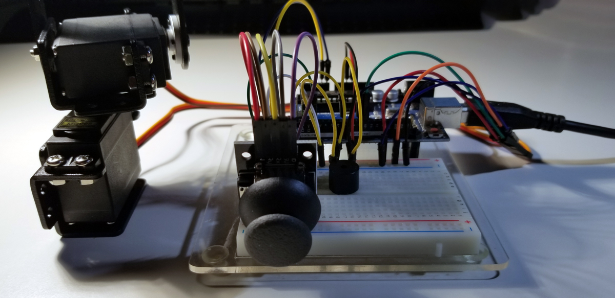
The active buzzer sounds when the joystick is depressed. It acts as a toggle to represent a select function that corresponds to typical X,Y positioning at a specific point along its movement.
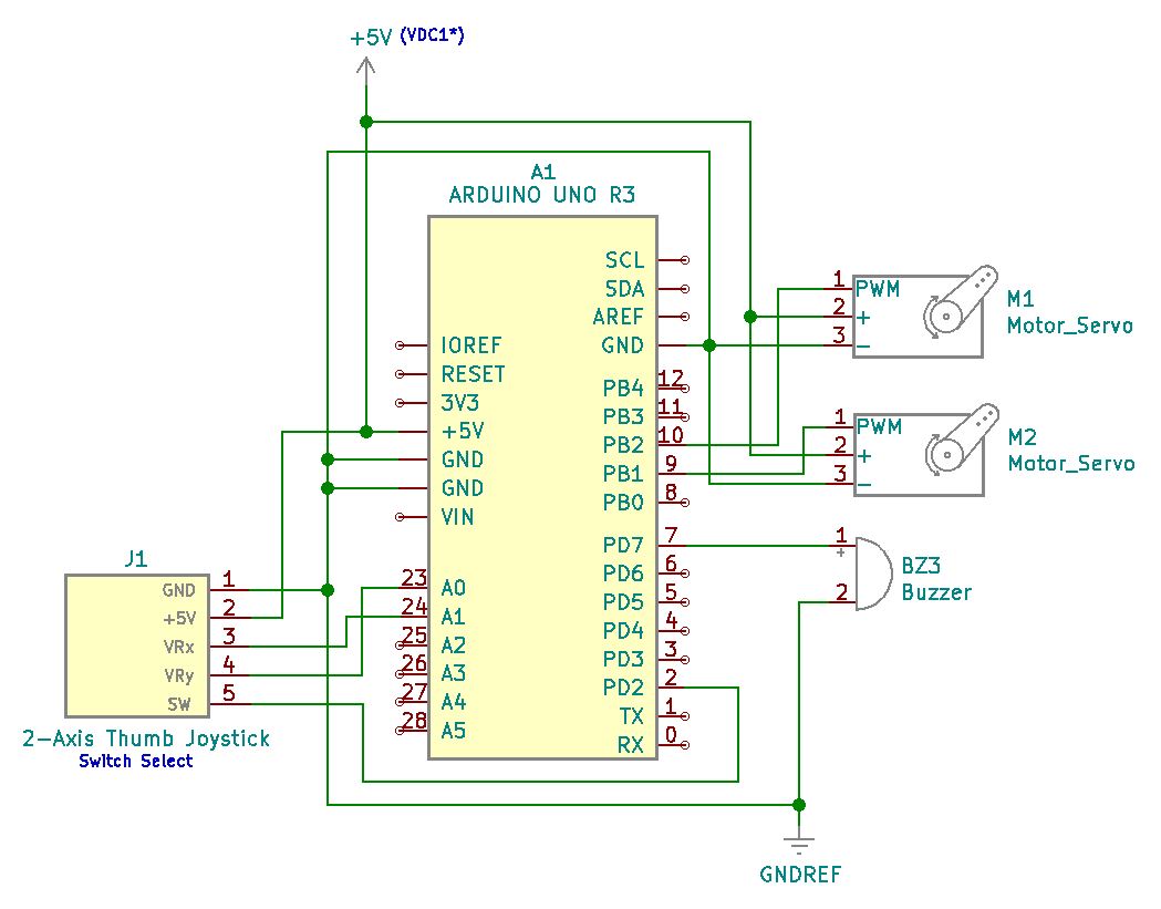
Project Schematic:
Through pulse width modulation pin connections on the Arduino, simultaneously movement control is achieved at both servos. Along with voltage and ground connections shared with the joystick, separate analog connections are terminated for analogRead instructions at the Arduino controller.
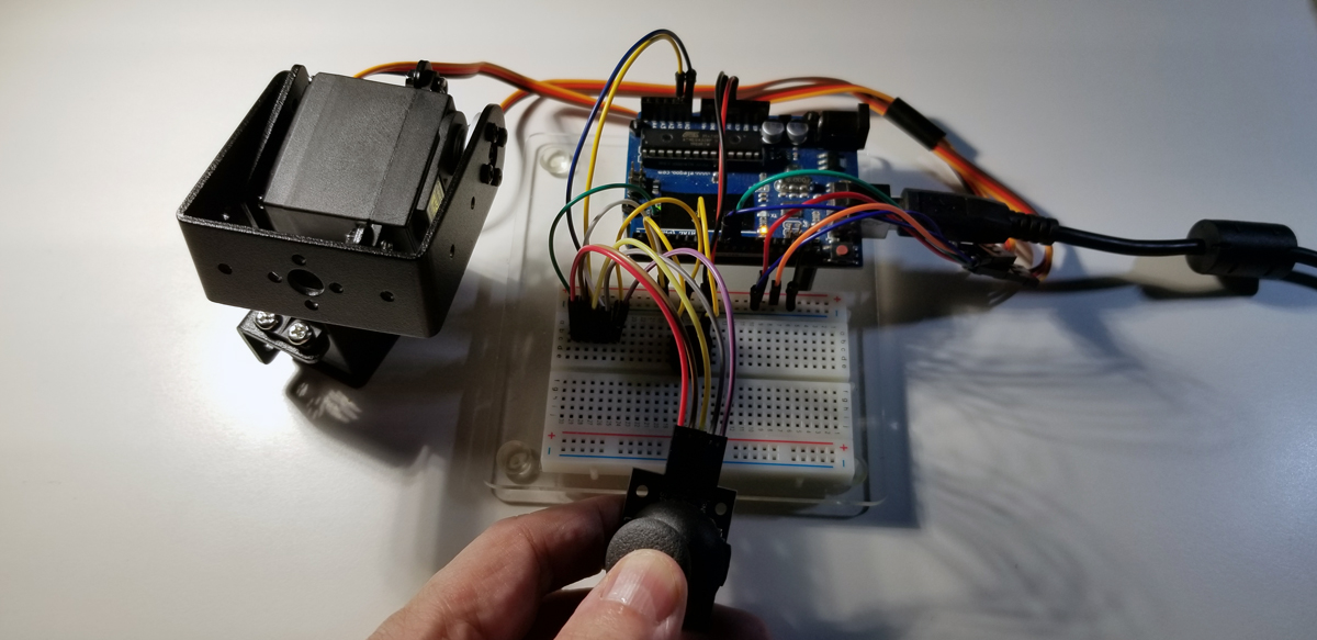
Project Review:
This video demonstrates the servo motor’s range of motion and precise positioning as the joystick is controlled with its push-button switch.
Code Example:
#include <Servo.h>
Servo Xservo;
Servo Yservo;
int Xpin=A0;
int Ypin=A1;
int Spin=2;
int XSpin=9;
int YSpin=10;
int buzzPin=7;
int WVx;
int WVy;
int Xval;
int Yval;
int Sval;
int dt=200;
void setup()
{
Serial.begin(9600);
pinMode(Xpin,INPUT);
pinMode(Ypin,INPUT);
pinMode(Spin,INPUT);
pinMode(XSpin,OUTPUT);
pinMode(YSpin,OUTPUT);
pinMode(buzzPin,OUTPUT);
Xservo.attach(XSpin);
Yservo.attach(YSpin);
digitalWrite(Spin,HIGH);
}
void loop() {
Xval=analogRead(Xpin);
WVx=(180./1023.)Xval; Yval=analogRead(Ypin); WVy=(180./1023.)Yval;
Sval=digitalRead(Spin);
Xservo.write(WVx);
Yservo.write(WVy);
if (Sval==0)
{
digitalWrite(buzzPin, HIGH);
}
else
{
digitalWrite(buzzPin, LOW);
}
delay(dt);
Serial.print(“X Value = “);
Serial.print(Xval);
Serial.print(” Y Value = “);
Serial.print(Yval);
Serial.print(” Switch State is “);
Serial.println(Sval);
}


