This project sets up a continuously monitored voltage level change at a potentiometer as derived from a source reference. As continuously variable voltage level changes, voltage levels are read into memory from an analogRead operation. From memory, those levels are read and compared to an assigned maximum value (1000). If an increase of voltage is exceeded beyond that value (by potentiometer control), the alarm triggers with a corresponding notice within the serial monitor.
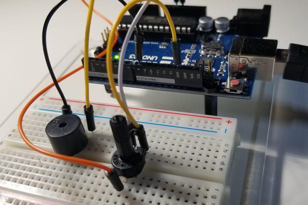
Active buzzer and potentiometer connectivity to Arduino UNO. Analog GPIO pin A3 and digital GPIO pin 8 attached to potentiometer and DC buzzer respectively. This is no a passive buzzer which requires and AC signal.
Both devices require a ground path while only the potentiometer requires its reference 5VDC. The wiper pin of the pot is connected to the A3 GPIO port.
Program & Functional Operation:
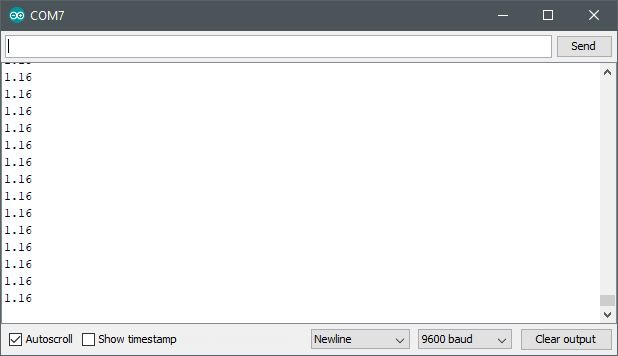
This video demonstrates how the code corresponds to the running levels that appear at the Serial Monitor. Notice the code specifies a 1000 limit to the analogRead of the potentiometer level value. Further along in the video, the potentiometer control is rotated to indicate an exceeded level until rotated back below that value again.
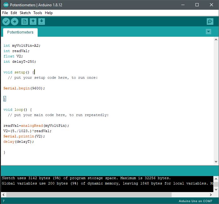
Code set up in the Arduino IDE (Sketch).Continuously scrolled level increases or decreases as values are read into memory via analogRead from the potentiometer control.
With the use of a potentiometer (trim-pot), it is possible to control a voltage level presented to an external circuit from a reference supply voltage connected to an Arduino unit. Through the use of a trim-pot, a supply voltage scales up or down between 0V and the supply voltage (5VDC) by continuous rotation of its control shaft or wiper.
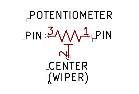
The three pins or leads of a potentiometer are connection points to a supply or circuit elements for purposes of voltage and signal control. Two outer leads are each end of the potentiometer’s total resistive element. The center pin serves as a connection for a wiper that internally travels between each outer point. As a potentiometer shaft or wiper is rotated, the resistance at the center point provides for a change in voltage level at that wiper connection. Where the resistance is the total between two points as given by the symbolic illustration below. Connections made between pins 1 and 2 or pins 2 and 3 are therefore always lower in resistance than connections made between pins 1 and 3. As the wiper shaft is rotated between pins 1 and 3, the resistance, therefore, changes between either of the two pins 1 or 3. So any voltage present across either pair of pins will become scaled to either the highest or lowest voltage. Since according to ohm’s law, resistance is directly proportional to voltage, the higher the resistance between two pins, the greater the voltage becomes present between those two points.
As a side matter of interest, it is necessary to recognize that the taper of the potentiometer affects the rate by which resistance or voltage changes as a wiper control is rotated. So, both linear or log continuously variable potentiometers or trim-pots are available to affect the rate in which control changes can occur. Potentiometers are also at times detented or non-detented depending upon what is selected. Detented pots are clicked into each rotated position as a control wiper is moved from one position to the next as it is rotated. More information about the theory and operation of potentiometers can be found here.
Schematic Symbol of Potentiometer
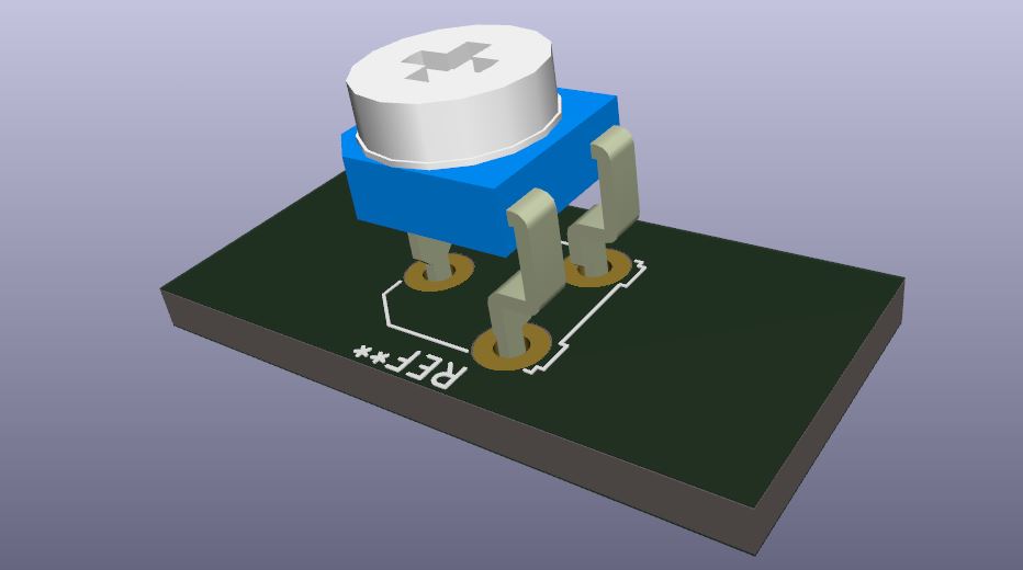
3D Rendering of Trim Pot Potentiometer
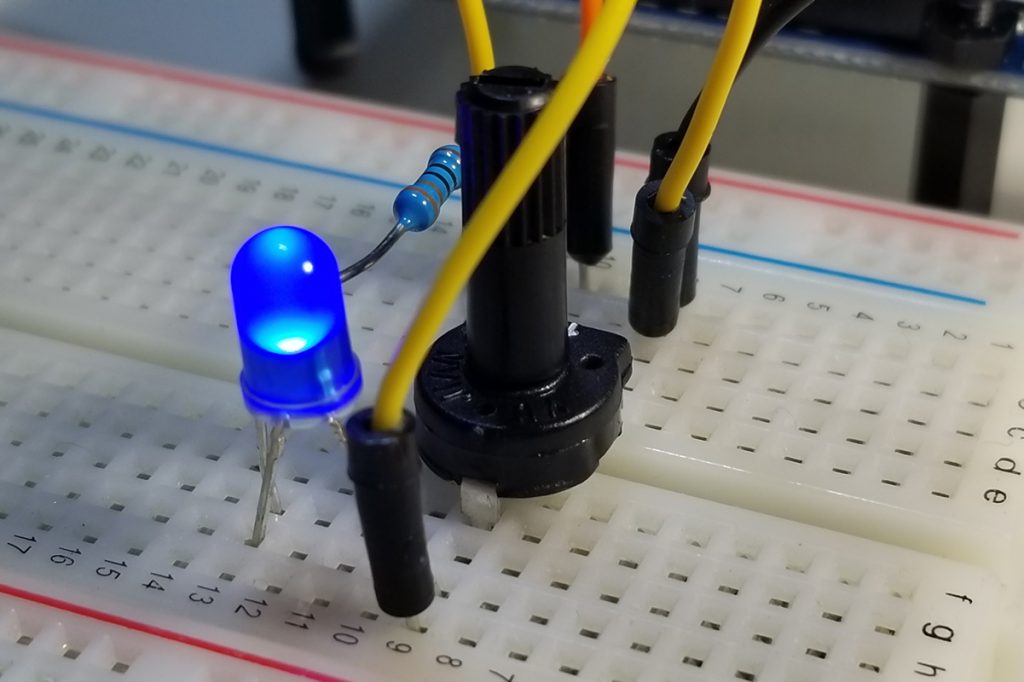
A demonstration of voltage control is demonstrated in the video below. As the wiper is rotated, the voltage level presented at the center pin of the trim pot is changed within the limits of 0VDC to the maximum voltage (5VDC). In this instance, an LED is connected to the wiper pin and its illumination level is increased or decreased as a function of voltage level.
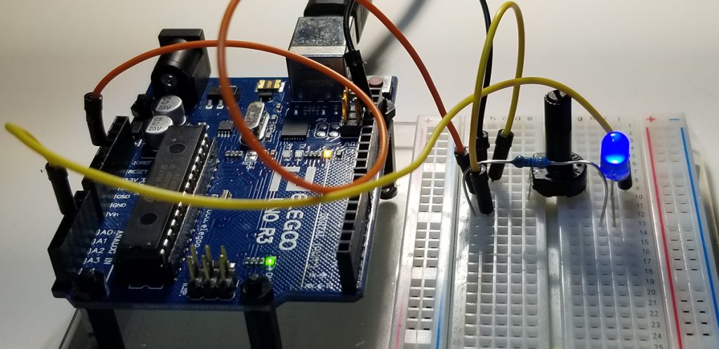
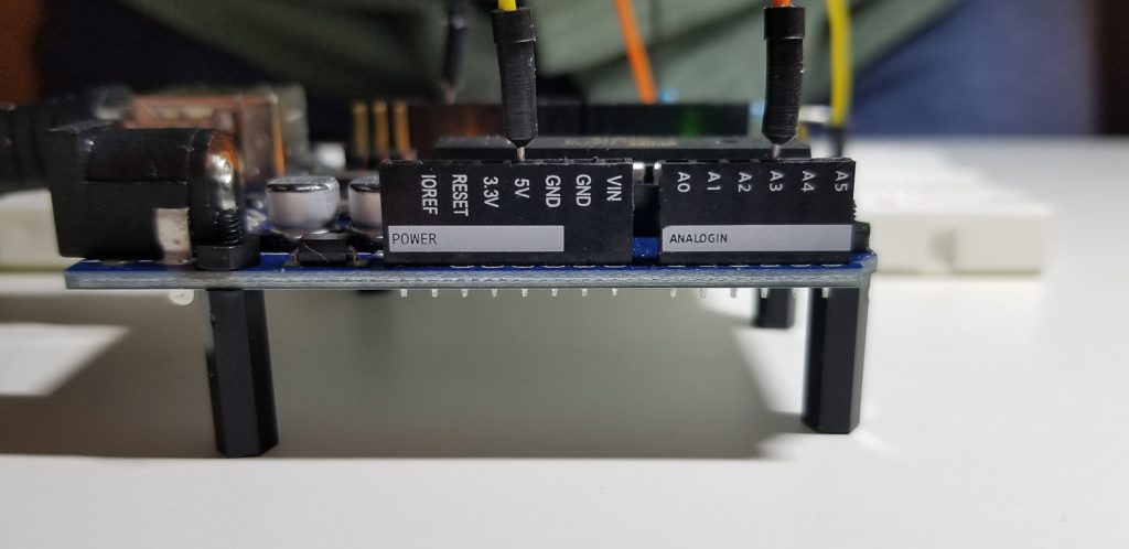
To build the circuit and operate the control, simple connections are made between an Arduino UNO and its external components as depicted below. The purpose of the Arduino is to provide the source voltage and connections for voltage level readout using the analogRead command.
Hardware Setup:
Simple Connectivity of LED to Potentiometer / Trim Pot
Circuit Set Up of Arduino and Trim Pot for Voltage Readout and LED Illumination
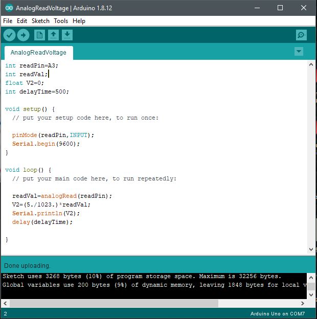
The code set up involves the configuration as written about previously in a prior post. The setups involve the three areas of interest to include variable declarations by datatype, system communication rate (9600 BAUD) between a host computer, and the Arduino’s serial monitor via the Sketch IDE. Finally, the operating code provides the instructions and commands by which operations are performed.
Code Setup:
int myVoltPin=A2; int readVal; float V2; int delayT=250;
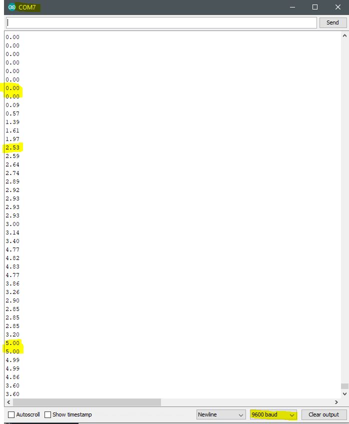
Code set up in the Arduino IDE (Sketch).Continuously scrolled voltage values presented as potentiometer wiper is rotated. To demonstrate the voltage scale and range as a function of analogRead operation.
A useful way of reading a voltage signal level is through an Analog Input port on the Arduino. With accompanied code to collect, interpret, calculate, display, and act upon a static of dynamic voltages from a circuit, discrete numerical values are presented to a user. In this project, those values are displayed via the Arduino Sketch Serial Monitor. As necessary to bring those values together, in an effort to read an actual voltage, it is necessary to build a circuit or tap an existing circuit, and write the code to get the readings desired. In this case, it is important to also perform a conversion of read values from binary equivalent numbers due to the Arduino UNO in this project that uses a 10-bin A/D converter (210 – 10-bit resolution or 1024 distinct values for a single point of measurement).
There are numerous basic applications from this function as a separate or partitioned segment of capability that pertains to other relevant purposes. The reason it is so important to understand this capability is because of its relevance as a fundamental building block elsewhere. Just as there are many other building blocks, this is a key capability that has a bearing on how projects come together using both a combination of hardware and software.
This code includes variables to initialize conditions by which the entire program operates. These variables must be declared using a data type that specifies how they are acted upon. In this example, integer and float data types get declared to establish precision for accuracy and proper computations or handling. Afterward, the program involves set up commands to configure the program and operate functions as intended. Finally, the void loop() function provides for the instructions to execute programmatically.
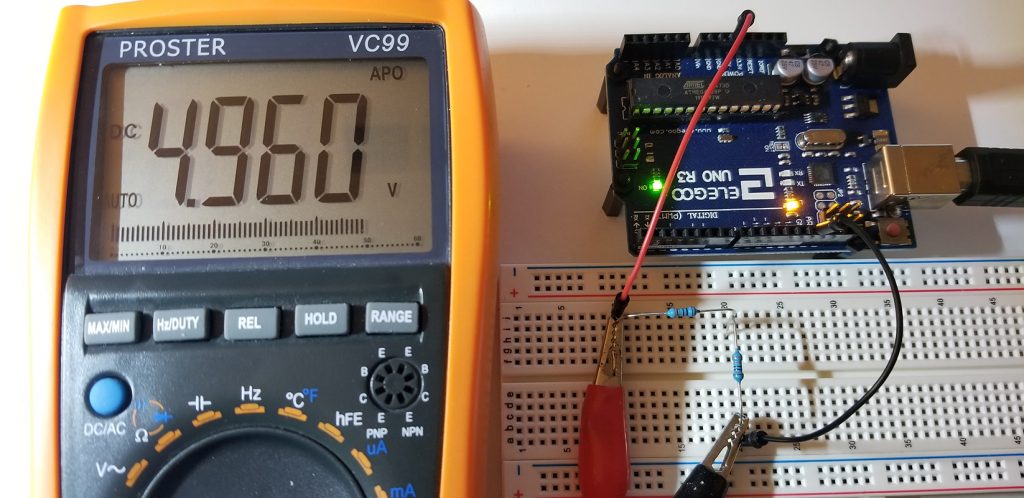
In this example, under the void loop(), the physical voltage read into the analog port is the value presented to the analog-to-digital converter. As this value is stored into variable memory readVal, it is multiplied by a coefficient (5./1023.). This calculation becomes necessary as the numerical value read into the readVal memory isn’t a voltage level as given by a meter. So, the calculation of 5VDC ÷ 1023 values gives a ratio of two maximum values as represented as voltage (numerator) and resolution (denominator). This calculation normalizes the digital value read at the analog port input to a voltage value read into memory (V2) or displayed as desired. V2, in turn, is read out at the serial monitor utility from the Arduino Sketch IDE to make tangible the entire operation. Meaning, a readout of voltage using an Arduino module and a host computer instead of a separate dedicated meter.
// declare variables int readPin=A3; int readVal; float V2=0; int delayTime=500;
void setup() { // put setup code here, to run once while using any relevant variable declared above
pinMode(readPin,INPUT); Serial.begin(9600); }
void loop() { // put main code here, to run repeatedly. runs in a continuous loop until interrupted or physically halted
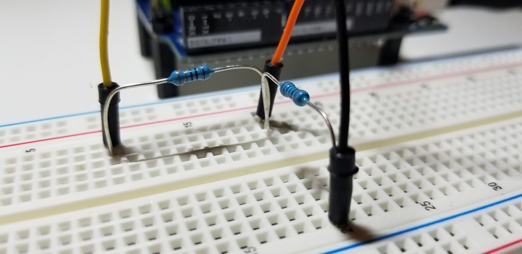
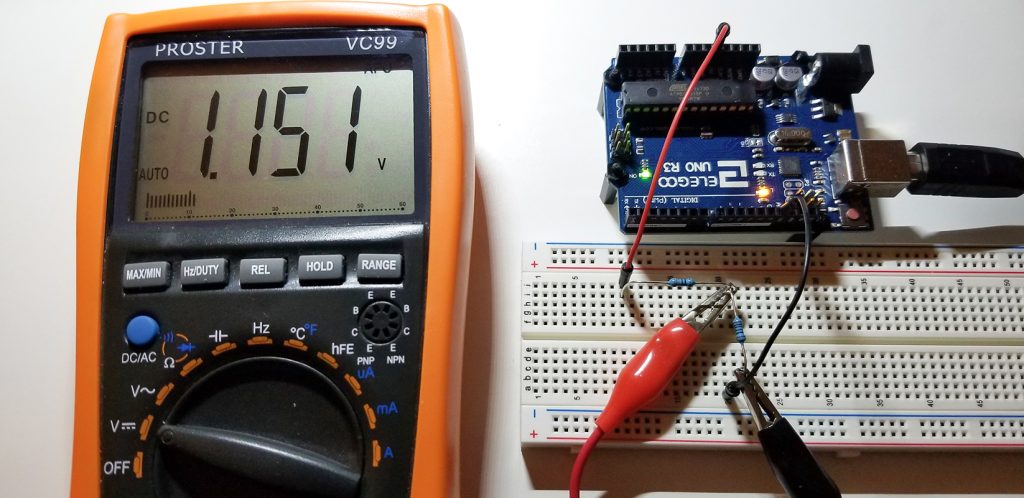
Stable Circuit Operating VoltagePort Connections. Reference Voltage & Analog Input VoltageSimple Voltage Divider Circuit (330Ω & 100Ω)Code Implementation of Voltage MeterSelected Voltage Value for Arduino AnalogReadSerial Monitor Value Reading from Arduino AnalogRead