This project involves a toggle switch that an Arduino UNO recognizes through code as necessary to activate an LED over a GPIO pin. Assembly of the circuit requires a 330 resistor, 10K resistor, normally open pushbutton switch, and a red LED plus some jumpers. For added clarity about the assembly refer to the photos below. The schematic illustration merely offers a symbolic representation of the setup. The prior project involved the use of pushbutton switch that temporarily enabled an output (LED) from a GPIO pin.
This project changes the state of the GPIO (LED) each time the pushbutton is pressed. The pushbutton switch in this way operates as a toggle as a steady-state on/off through conditional instruction statements written into the code.
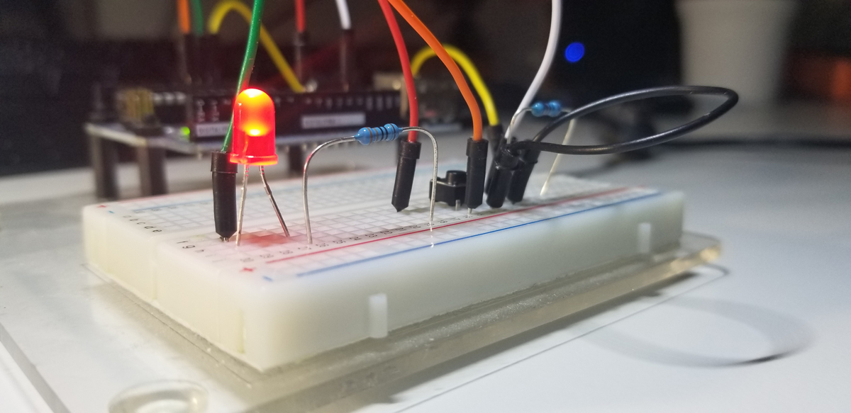
Simple set up of a small circuit to interface with the Arduino UNO R3 SBC. Includes 330 ohm, 10K ohm current limiting resistors, a RED LED, and a small pushbutton normally open switch. Circuit jumpers interface to the Arduino’s GPIO ports.
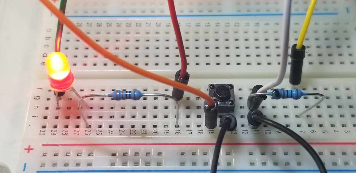
Top down view of circuit connections.
To register active high and active low states at a GPIO port, it is necessary to apply pull up or pull-down resistors to a circuit’s normally open or normally closed pushbutton switch. It is not an acceptable practice to place a GPIO pin directly to a +5V source, or Ground in order to operate a directly connected switch. The purpose of a pulldown or pullup resistor placed onto a switch is to correctly register an active high or low state at an assigned GPIO measurement pin. To illustrate the connections see the diagrams below:
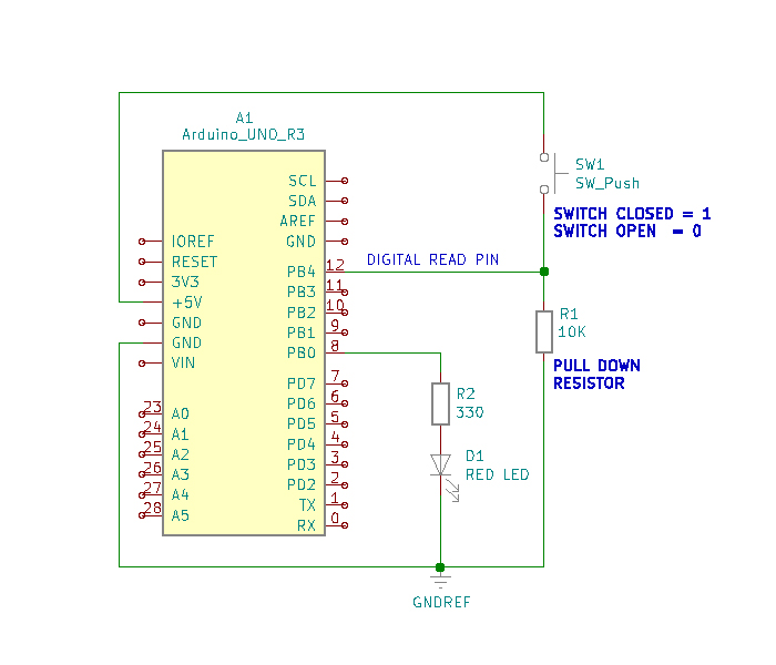
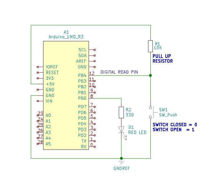
Simply put, there just must be a circuit path to either a voltage reference or ground reference using a resistor connected to a switch for proper operation. The active voltage present at pin-12, while the button switch is not pressed, is 5VDC. When the pushbutton switch is pressed this voltage level drops to 0VDC. As a 0VDC state is read into pin 12 by the digitalRead operation (i.e. pin 12 becomes grounded), pin 8 presents 5VDC to R2 for the Red LED to illuminate. While the pushbutton switch is pressed and held closed, the serial monitor presents a digital “0” state. This is due to the placement of the digitalRead command within the continuous program loop.
To run the project it is necessary to assemble the circuit onto a breadboard using the components identified above. When the hardware is set up, it is then necessary to write and run the code to get functional use of the project.
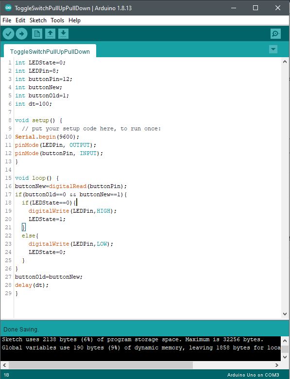
Code Setup:
int LEDState=0;
int LEDPin=8;
int buttonPin=12;
int buttonNew;
int buttonOld=1;
int dt=100;
void setup() {
// put your setup code here, to run once:
Serial.begin(9600);
pinMode(LEDPin, OUTPUT);
pinMode(buttonPin, INPUT);
}
void loop() {
buttonNew=digitalRead(buttonPin);
if(buttonOld==0 && buttonNew==1){
if(LEDState==0){
digitalWrite(LEDPin,HIGH);
LEDState=1;
}
else{
digitalWrite(LEDPin,LOW);
LEDState=0;
}
}
buttonOld=buttonNew;
delay(dt);
}
With all suitable integer variables declared, operational instructions become written to perform their intended purpose. Standard pin mode set up declarations are made, and thereafter, the main loop program begins.
The digitalRead operation is executed as the buttonPin command is asserted. The physical state change that occurs from the button switch is detected at the Arduino port (pin 12) and that change is digitally read into memory and stored to the buttonNew variable. Once a switch state is read into memory via the GPIO port, the next set of instructions act upon those states held into memory.
The if-else statement parameters check for the high or low (5VDC or 0VDC) level presented to GPIO pin 12. As the buttonOld and buttonNew variables are checked for true status against assigned states “0” to buttonOld and “1” to buttonNew, the next if-statement is executed. The LEDState is checked for a logic 0 state and if it is true, the digitalWrite command places a HIGH state (logic 1, 5VDC) to the LEDPin (pin 8) GPIO port. The LEDState is then given a logic 1 into its memory space to initialize it for repeat evaluation during the continuous loop in function. Once the true state instructions are executed within both ‘if’ commands, the program falls through the function to bypass the ‘else’ code segment and continues through to the rest to the program until completion where the loop again begins.
The second half of the conditional function, ‘else’ supports the logic evaluation that previously occurred between the buttonNew and buttonOld ‘recognized’ states. If the combination of both variable assessments proves false, the else statement becomes effective within the loop to set the LEDPin to Low. This is the equivalent of a logic evaluation that checks for voltage transitions low to high and turn the LED off. Each time this transition occurs, the program loop writes the active high to turn the LED on or off. The next low-to-high button switch transition evaluation occurs within the ‘else’ segment of the conditional loop to again set the GPIO pin to low (pin-8 LED off) if that else condition should become true.
As the program loop continuously runs, the GPIO pin accepts state changes to operate as a toggle on and off, then on and off again.
Arduino IDE: