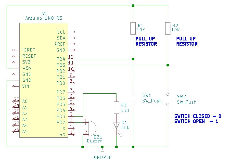
This project controls an increasing and decreasing voltage level in increments to represent a dimmer present at an LED. An in-circuit buzzer serves as an alarm to indicate either a maximum or minimum level is attained. Two separate pushbutton switches are up / down controls at programmable increments.
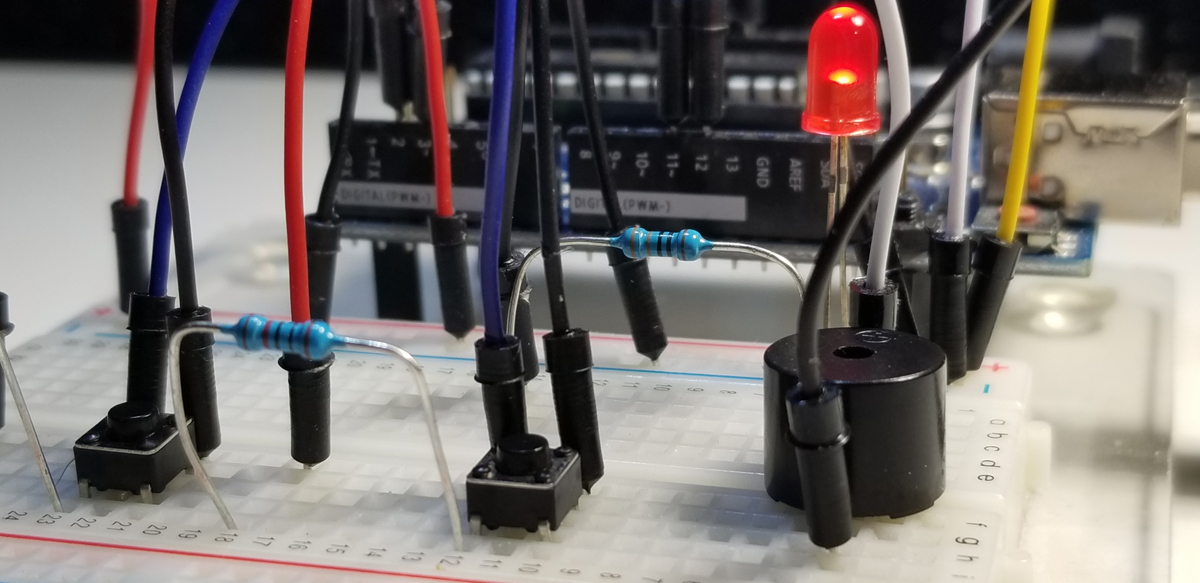
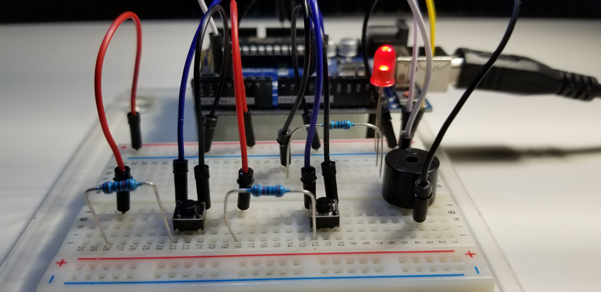
One pull up resistor for each pushbutton switch is necessary to correctly assert each GPIO input to control circuit and code activity. Four total GPIO pins used, each one for its dedicated function. There is no attempt to make dual use of a GPIO port.
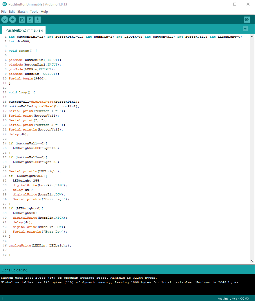
Program & Functional Operation:
Code Setup:
int buttonPin1=12;
int buttonPin2=11;
int buzzPin=2;
int LEDPin=3;
int buttonVal1;
int buttonVal2;
int LEDbright=0;
int dt=500;
void setup() {
pinMode(buttonPin1,INPUT);
pinMode(buttonPin2,INPUT);
pinMode(LEDPin,OUTPUT);
pinMode(buzzPin, OUTPUT);
Serial.begin(9600);
}
void loop() {
buttonVal1=digitalRead(buttonPin1);
buttonVal2=digitalRead(buttonPin2);
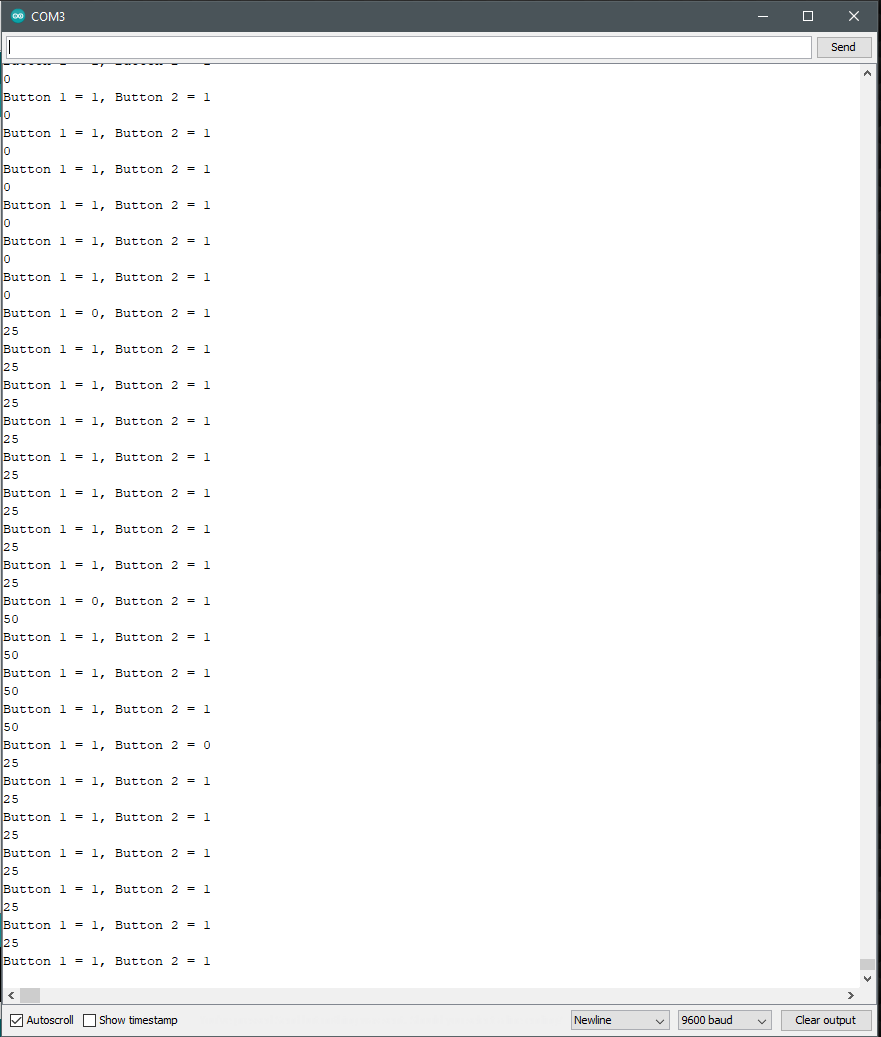
Serial.print(“Button 1 = “);
Serial.print(buttonVal1);
Serial.print(“, “);
Serial.print(“Button 2 = “);
Serial.println(buttonVal2);
delay(dt);
if (buttonVal1==0){
LEDbright=LEDbright+25;
}
if (buttonVal2==0){
LEDbright=LEDbright-25;
}
Serial.println(LEDbright);
if (LEDbright>255){
LEDbright=255;
digitalWrite(buzzPin,HIGH);
delay(dt);
digitalWrite(buzzPin,LOW);
Serial.println(“Buzz High”);
}
if (LEDbright<0){
LEDbright=0;
digitalWrite(buzzPin,HIGH);
delay(dt);
digitalWrite(buzzPin,LOW);
Serial.println(“Buzz Low”);
}
analogWrite(LEDPin, LEDbright);
}
Arduino Set Up: