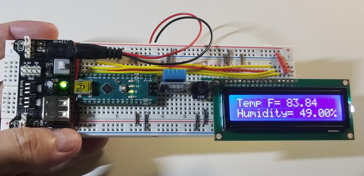
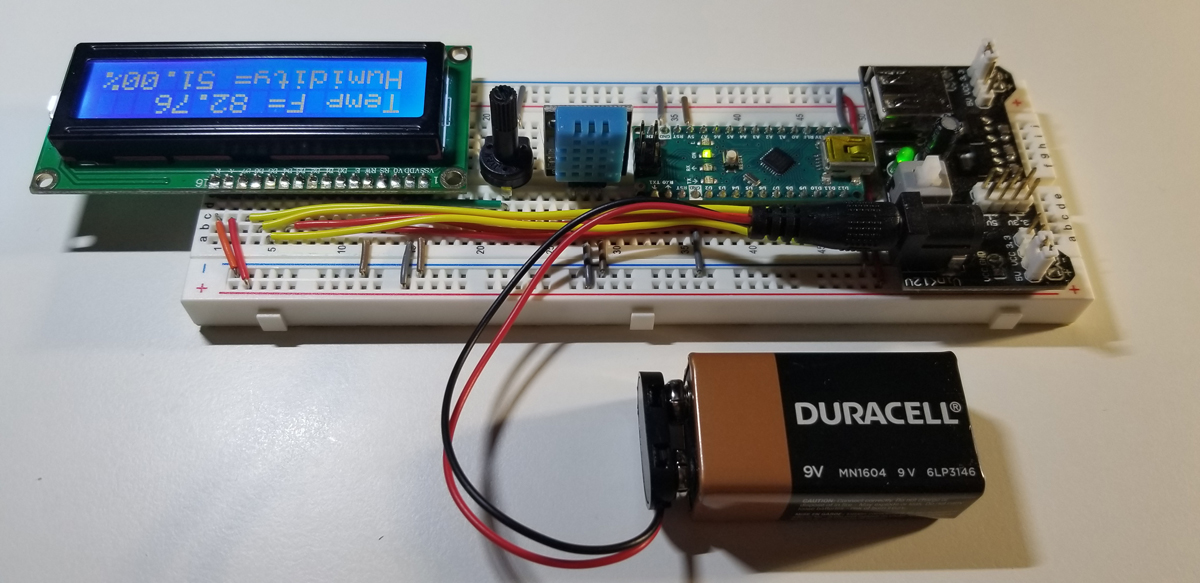
The purpose of this build is to become more familiar with how to develop a free-standing Arduino system using the Arduino Nano. The Nano is a smaller equivalent to the Arduino Uno, but with fewer interface options. It obviously occupies less space since it is a smaller footprint while having reduced overall dimensions. The project makes use of a DHT temperature and humidity sensor that interfaces with the Nano and it includes a 16×2 LCD display to indicate measurement results.
1602A LCD Display Pinout
| Pin | Symbol | Function |
|---|---|---|
| 1 | VSS | Ground |
| 2 | VDD | +5VDC |
| 3 | V0 | Contrast |
| 4 | RS | Register |
| 5 | R/W | Read/Write |
| 6 | E | Enable |
| 7 | D0 | Data |
| 8 | D1 | Data |
| 9 | D2 | Data |
| 10 | D3 | Data |
| 11 | D4 | Data |
| 12 | D5 | Data |
| 13 | D6 | Data |
| 14 | D7 | Data |
| 15 | A | Anode (+5VDC) |
| 16 | K | Cathode (Ground) |
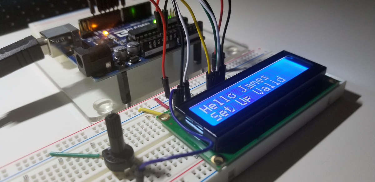
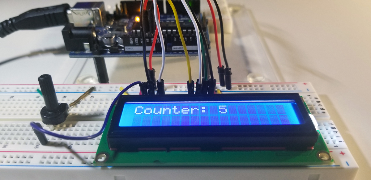
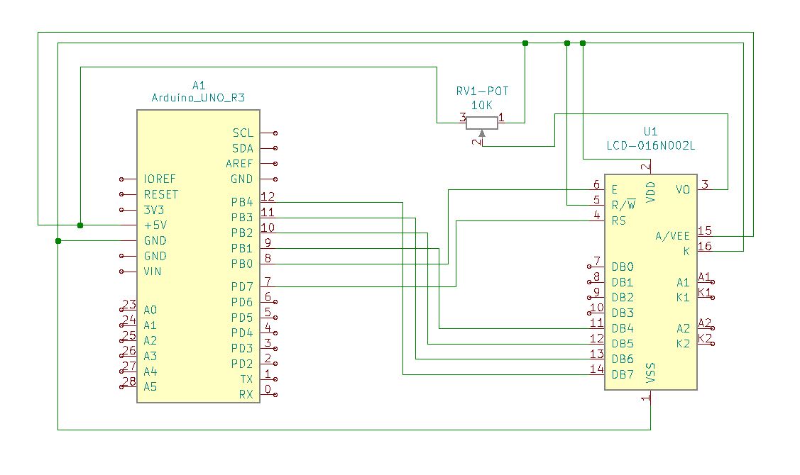
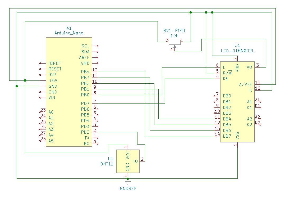
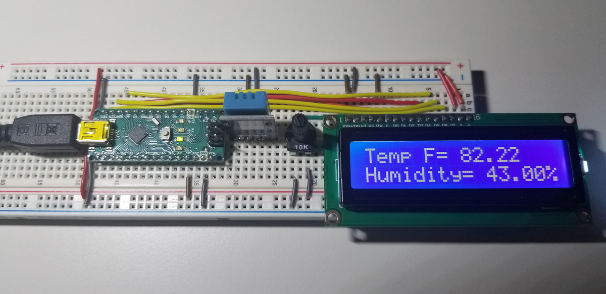
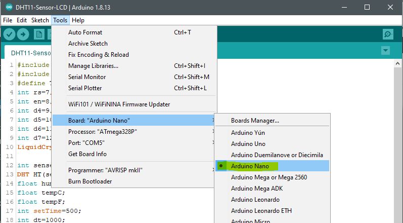
Arduino Setup:
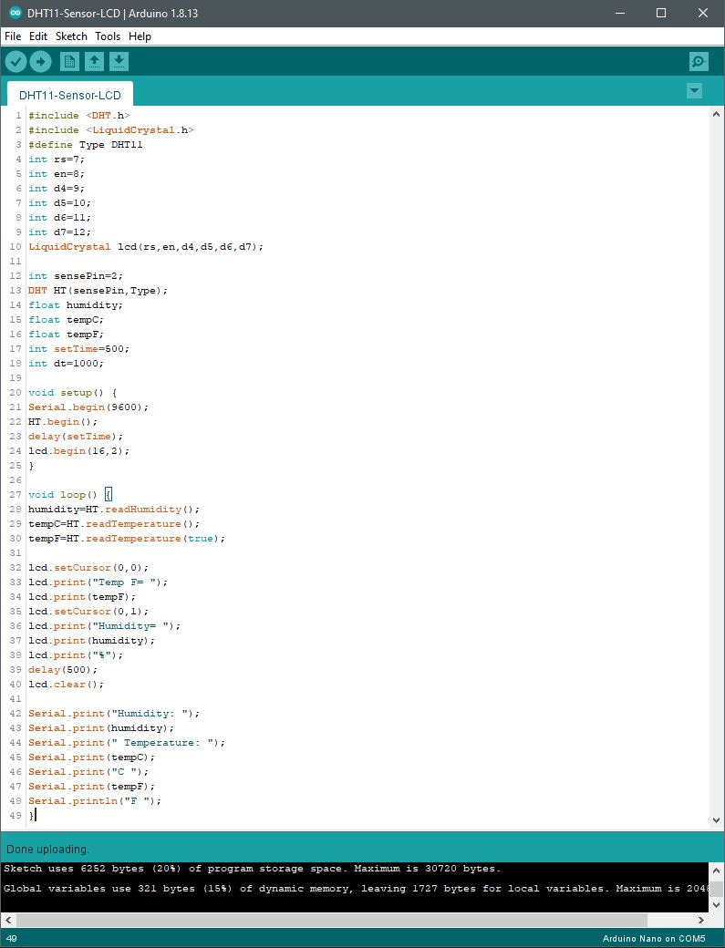

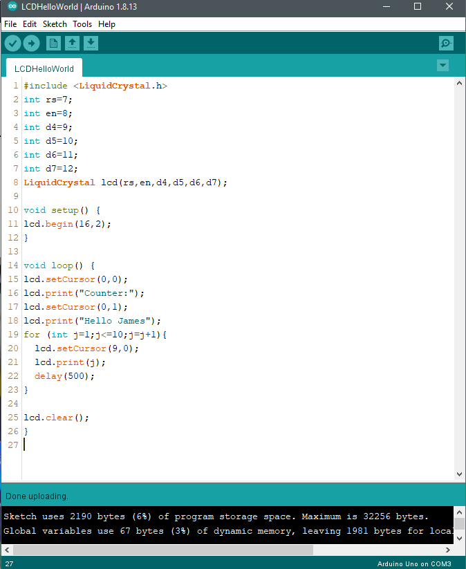
Code Setup:
#include <DHT.h>
#include <LiquidCrystal.h>
int rs=7;
int en=8;
int d4=9;
int d5=10;
int d6=11;
int d7=12;
LiquidCrystal lcd(rs,en,d4,d5,d6,d7);
int sensePin=2;
DHT HT(sensePin,Type);
float humidity;
float tempC;
float tempF;
int setTime=500;
int dt=1000;
void setup() {
Serial.begin(9600);
HT.begin();
delay(setTime);
lcd.begin(16,2);
}
void loop() {
humidity=HT.readHumidity();
tempC=HT.readTemperature();
tempF=HT.readTemperature(true);
lcd.setCursor(0,0);
lcd.print(“Temp F= “);
lcd.print(tempF);
lcd.setCursor(0,1);
lcd.print(“Humidity= “);
lcd.print(humidity);
lcd.print(“%”);
delay(500);
lcd.clear();
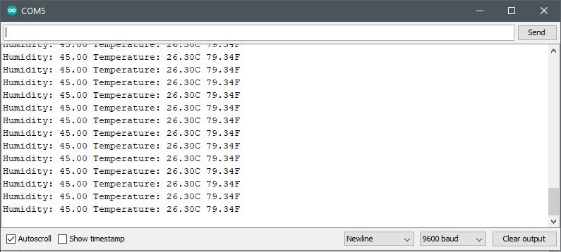
Serial.print(“Humidity: “);
Serial.print(humidity);
Serial.print(” Temperature: “);
Serial.print(tempC);
Serial.print(“C “);
Serial.print(tempF);
Serial.println(“F “);
}