This project accomplishes a few objectives. First, the use of a KY-022 Infrared sensor is incorporated for general familiarity. Second, the IR remote control emits HEX codes for each button pressed, so it is necessary to capture those HEX codes to map them to specific button IDs and functions later developed. Third, to integrate the motor control driver (L293D) with the Arduino Nano to control motor activity such as speed and direction.
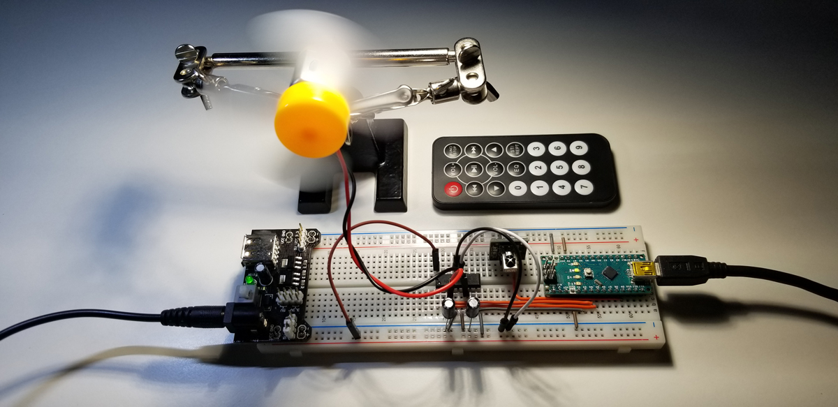
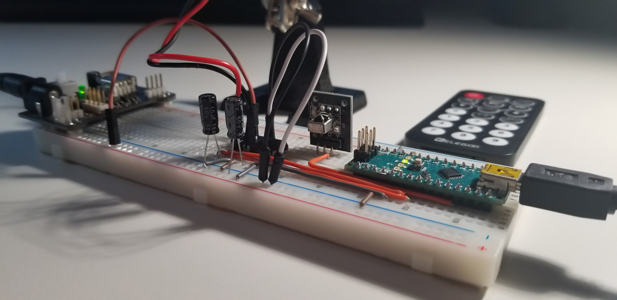

Arduino Setup:
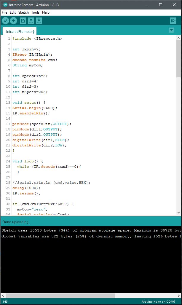


Code Setup:
#include <IRremote.h>
int IRpin=9;
IRrecv IR(IRpin);
decode_results cmd;
String myCom;
int speedPin=5;
int dir1=4;
int dir2=3;
int mSpeed=205;
void setup() {
Serial.begin(9600);
IR.enableIRIn();
pinMode(speedPin,OUTPUT);
pinMode(dir1,OUTPUT);
pinMode(dir2,OUTPUT);
digitalWrite(dir1,HIGH);
digitalWrite(dir2,LOW);
}
void loop() {
while (IR.decode(&cmd)==0){
}
//Serial.println (cmd.value,HEX);
delay(1000);
IR.resume();
if (cmd.value==0xFF6897) {
myCom=”zero”;
Serial.println(myCom);
}
if (cmd.value==0xFF30CF) {
myCom=”one”;
Serial.println(myCom);
}
if (cmd.value==0xFF18E7) {
myCom=”two”;
Serial.println(myCom);
}
if (cmd.value==0xFF7A85) {
myCom=”three”;
Serial.println(myCom);
}
if (cmd.value==0xFF10EF) {
myCom=”four”;
Serial.println(myCom);
}
if (cmd.value==0xFF38C7) {
myCom=”five”;
Serial.println(myCom);
}
if (cmd.value==0xFF5AA5) {
myCom=”six”;
Serial.println(myCom);
}
if (cmd.value==0xFF42BD) {
myCom=”seven”;
Serial.println(myCom);
}
if (cmd.value==0xFF4AB5) {
myCom=”eight”;
Serial.println(myCom);
}
if (cmd.value==0xFF52AD) {
myCom=”nine”;
Serial.println(myCom);
}
if (cmd.value==0xFFA25D) {
myCom=”pwr”;
Serial.println(myCom);
}
if (cmd.value==0xFF629D) {
myCom=”v+”;
Serial.println(myCom);
}
if (cmd.value==0xFFA857) {
myCom=”v-“;
Serial.println(myCom);
}
if (cmd.value==0xFFE21D) {
myCom=”func”;
Serial.println(myCom);
}
if (cmd.value==0xFF22DD) {
myCom=”rwd”;
Serial.println(myCom);
}
if (cmd.value==0xFF02FD) {
myCom=”play”;
Serial.println(myCom);
}
if (cmd.value==0xFFC23D) {
myCom=”ff”;
Serial.println(myCom);
}
if (cmd.value==0xFFE01F) {
myCom=”down”;
Serial.println(myCom);
}
if (cmd.value==0xFF906F) {
myCom=”up”;
Serial.println(myCom);
}
if (cmd.value==0xFF9867) {
myCom=”eq”;
Serial.println(myCom);
}
if (cmd.value==0xFFB04F) {
myCom=”st”;
Serial.println(myCom);
}
if (myCom==”pwr”){
digitalWrite(dir1,LOW);
digitalWrite(dir2,HIGH);
analogWrite(speedPin,205);
}
if (myCom==”func”){
digitalWrite(dir1,LOW);
digitalWrite(dir2,LOW);
analogWrite(speedPin,0);
}
if (myCom==”ff”){
digitalWrite(dir1,LOW);
digitalWrite(dir2,HIGH);
analogWrite(speedPin,mSpeed);
}
if (myCom==”rwd”){
digitalWrite(dir1,HIGH);
digitalWrite(dir2,LOW);
analogWrite(speedPin,mSpeed);
}
if (myCom==”up”){
mSpeed=mSpeed+5;
if (mSpeed>255){
mSpeed=255;
}
analogWrite(speedPin,mSpeed);
}
if (myCom==”down”){
mSpeed=mSpeed-5;
if (mSpeed<0){
mSpeed=0;
}
analogWrite(speedPin,mSpeed);
}
delay(500);
}


