This project makes use of a photoresistor as a light sensor to control the movement of a servo motor’s shaft. The change of position in the servo motor’s output shaft moves from 0 degrees to 180 degrees maximum depending upon the light intensity present at the photoresistor. The highest level of light places the output shaft arm to 0 degrees while the absence of light at the sensor moves the output shaft arm to about 180 degrees. The actual range of motion is limited to the quality of the servo, but 180 degrees is generally the limit.
All components in the system are powered by the Arduino Uno (R3) through the USB connection from a local supply or computer.
The purpose of the project is to demonstrate the simple use of a servo for the automatic positioning of a physical object as a function of light intensity. The light sensor is read at an analog GPIO pin to get continuously variable values to read into memory via an analogRead operation. The motor response to continuous analog read activity (with a small 250ms delay between each) is calculated to a PWM output level written to a port where the output shaft moves at a corresponding angle.
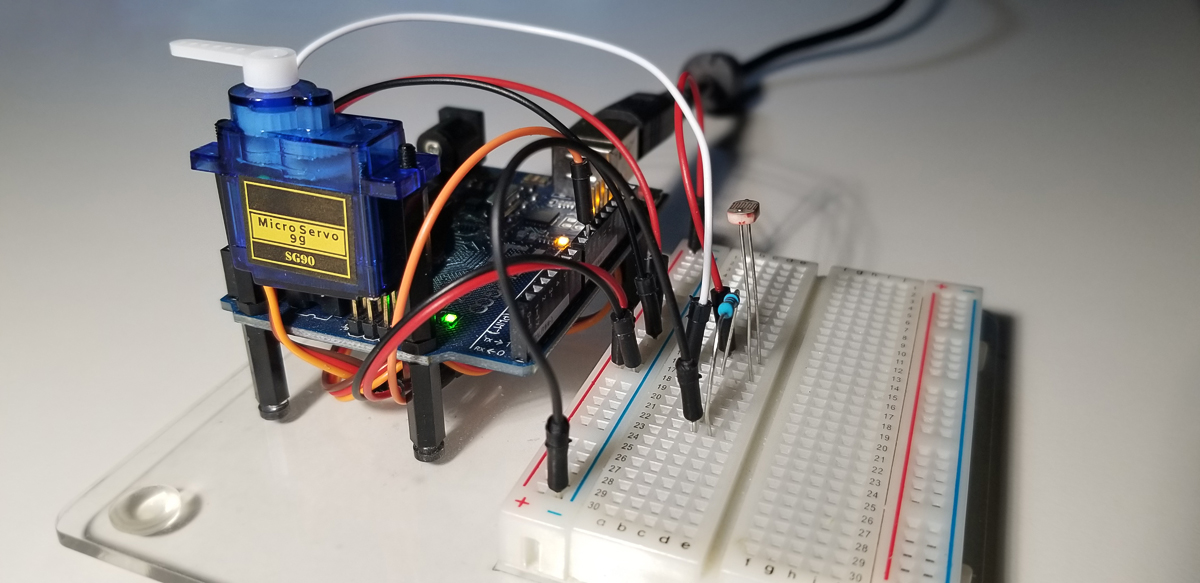
The micro servo mounts nicely onto the Arduino Uno in a secure way through the two standoffs on the controller. The various terminal connections in this photo correspond to the schematic diagram posted below.
The resistor is 5K-ohms with the analogRead connection between it and the photoresistor for active continuous input to the Arduino.
Project Operation:
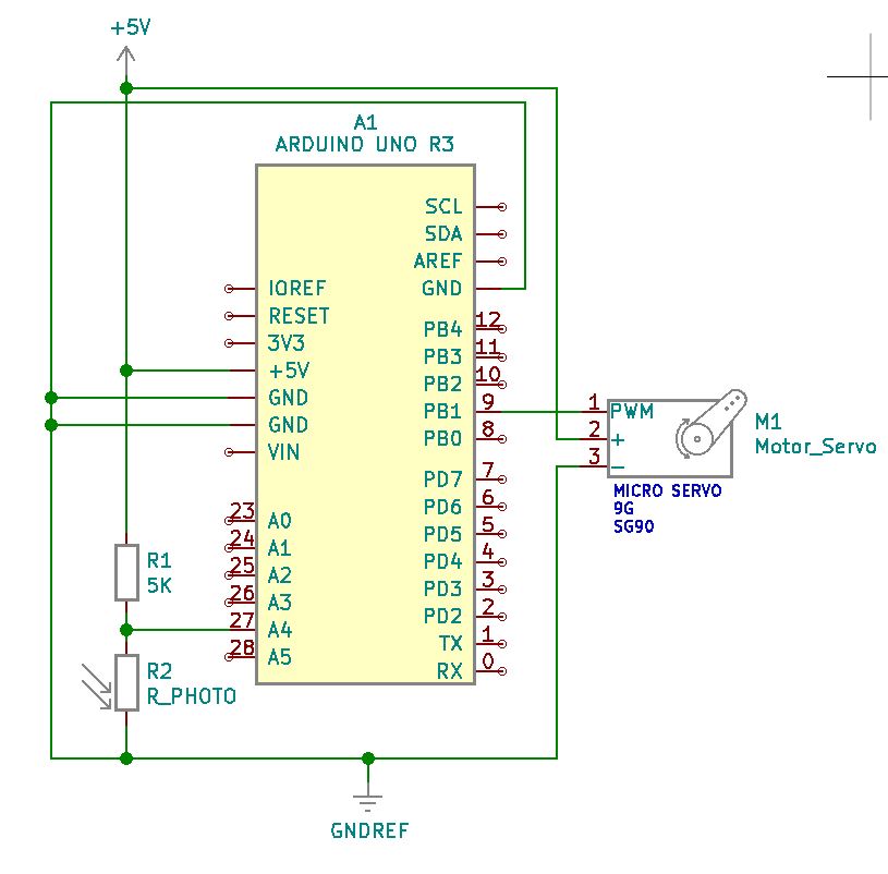
Project Schematic:
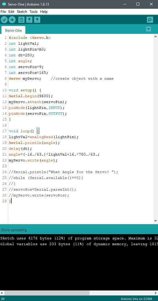
Arduino IDE:
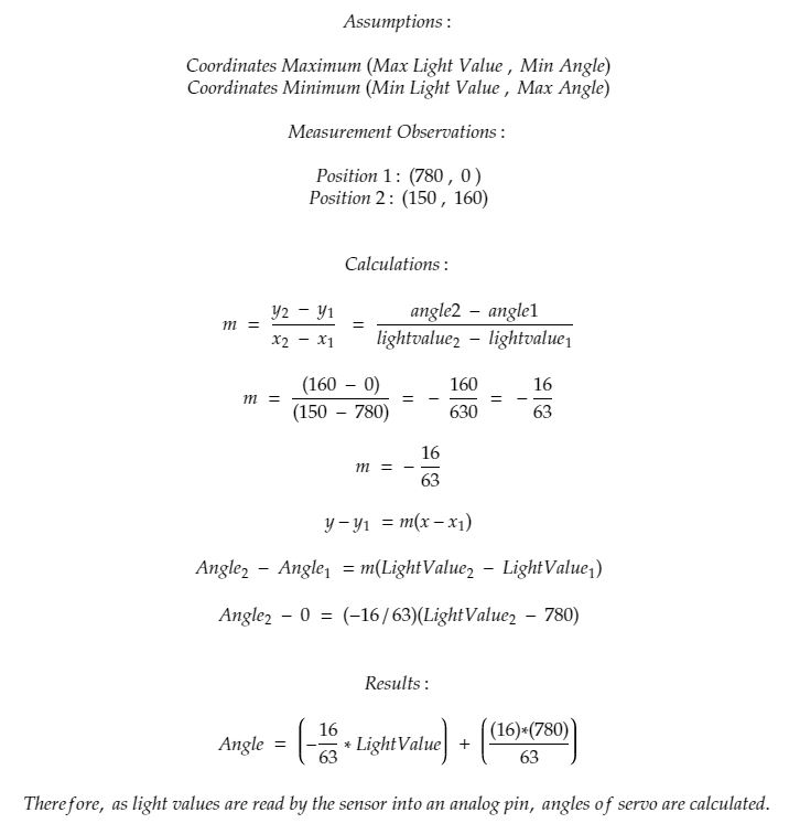
Servo Output Angle Calculations:
Code Setup:
#include <Servo.h> int lightVal; int lightPin=A4; int dt=250; int angle; int servoPin=9; int servoPos=165; Servo myServo; //create object with a name
Using the point-slope formula between the on-time and off-time of a passive buzzer, we can control the high frequency and low-frequency tone sound as a function of light. As a light source is drawn near to the photoresistor, the buzzer will increase in frequency. Conversely, as the light source is moved away from the photoresistor sensor, the buzzer sound will correspond to a low-frequency tone. Removal of the light source fully separated from the photoresistor permits an ambient light reading until the buzzer is fully settled to a maximally lower frequency of sound.
By experimenting with the point-slope formula in the code, you are able to change the tonality. However, to get a precise range and audible quality of the buzzer, it is best to calculate the on-time from a sample source reading at the sensor and an off-time (delay time) to complete each frequency cycle. The more cycles of on and off time, the higher the frequency.
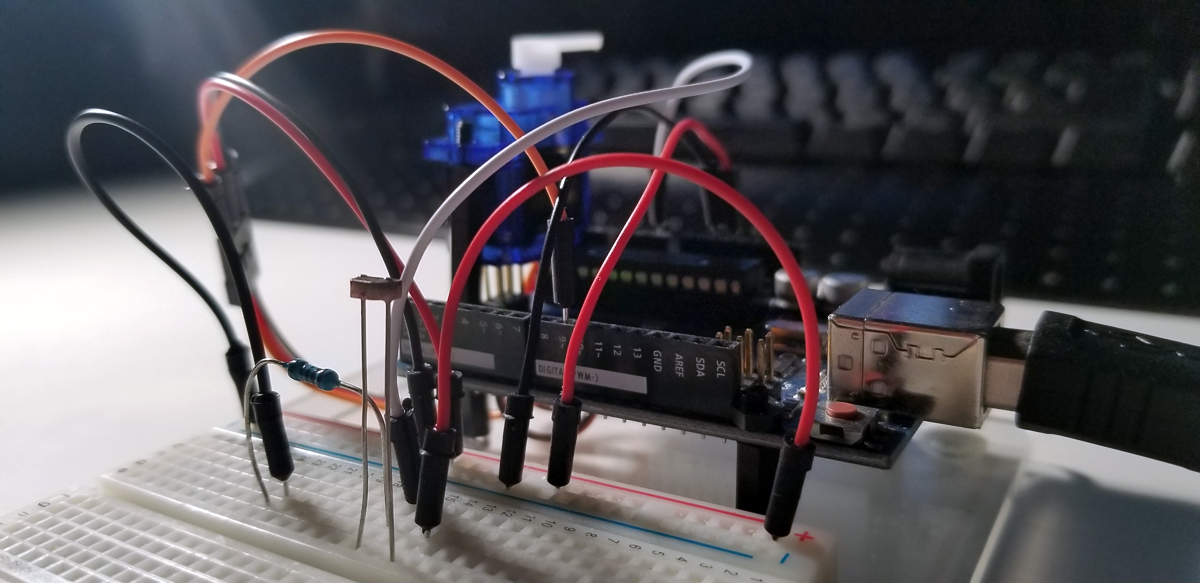
Simple component placement and wiring hook up.
5K Resistor in series with the photoresistor sensor. The Arduino UNO pin connected between the 5K resistor and the light sensor is reading a change in voltage present at this connection. The voltage divider changes value as the resistance of the light sensor increases or decreases. As the sensor’s resistance value decreases with increasing light levels, it conducts more and drops less voltage. The analogRead code instruction detects the change of voltage at this node and in turn produces change in tonality via the digitalWrite command at the output pin connected to the buzzer.
5K-ohm resistor in series with the photoresistor sensor and passive buzzer.
This is a passive buzzer that is driven by a voltage and light level separated by a delay between each digitalWrite event. Causing the buzzer to produce a tone of lower or greater frequency as new voltages are presented to it. Each new voltage level from the voltage divider produces its sound frequency by continuously turning the buzzer on and off again as it recognizes new levels as light intensity changes.
Light Sensor and resistor voltage divider input source. With separate buzzer output termination, the Arduino UNO module serves as the processing device for control via code instructions. ( Negative polarity terminal disconnected to interrupt operation).
Program & Functional Operation
This video demonstrates a change in buzzer tone as the light source distance from the light sensor is changed. The closer to the light sensor is exposed to a higher intensity of illumination, the higher the frequency in sound. The lower the light intensity, the lower the sound pitch or frequency.
Light & Delay Value Selection
To come up with a delay value for the integer variable declared in the code, it is necessary to the light sensor’s voltage value into memory via pin A0 on the Arduino. This means it is necessary to perform a calculation on the changes of input voltage levels as they change as light illumination intensity changes. The formula derivation is as follows:
-Paul McWhorter
Code Setup:
Copy & paste this code to your Arduino Sketch as desired to edit or experiment with your program.
int lightPin=A0; int buzzPin=8; int lightVal; int delayT;