With the use of a potentiometer (trim-pot), it is possible to control a voltage level presented to an external circuit from a reference supply voltage connected to an Arduino unit. Through the use of a trim-pot, a supply voltage scales up or down between 0V and the supply voltage (5VDC) by continuous rotation of its control shaft or wiper.
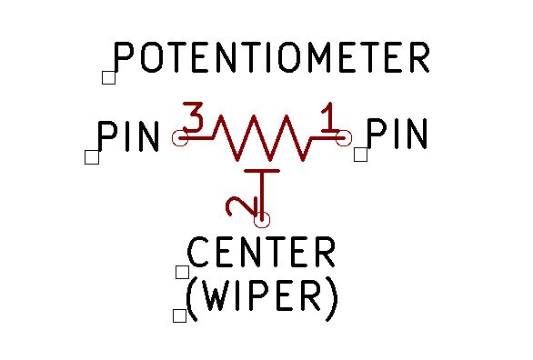
The three pins or leads of a potentiometer are connection points to a supply or circuit elements for purposes of voltage and signal control. Two outer leads are each end of the potentiometer’s total resistive element. The center pin serves as a connection for a wiper that internally travels between each outer point. As a potentiometer shaft or wiper is rotated, the resistance at the center point provides for a change in voltage level at that wiper connection. Where the resistance is the total between two points as given by the symbolic illustration below. Connections made between pins 1 and 2 or pins 2 and 3 are therefore always lower in resistance than connections made between pins 1 and 3. As the wiper shaft is rotated between pins 1 and 3, the resistance, therefore, changes between either of the two pins 1 or 3. So any voltage present across either pair of pins will become scaled to either the highest or lowest voltage. Since according to ohm’s law, resistance is directly proportional to voltage, the higher the resistance between two pins, the greater the voltage becomes present between those two points.
As a side matter of interest, it is necessary to recognize that the taper of the potentiometer affects the rate by which resistance or voltage changes as a wiper control is rotated. So, both linear or log continuously variable potentiometers or trim-pots are available to affect the rate in which control changes can occur. Potentiometers are also at times detented or non-detented depending upon what is selected. Detented pots are clicked into each rotated position as a control wiper is moved from one position to the next as it is rotated. More information about the theory and operation of potentiometers can be found here.
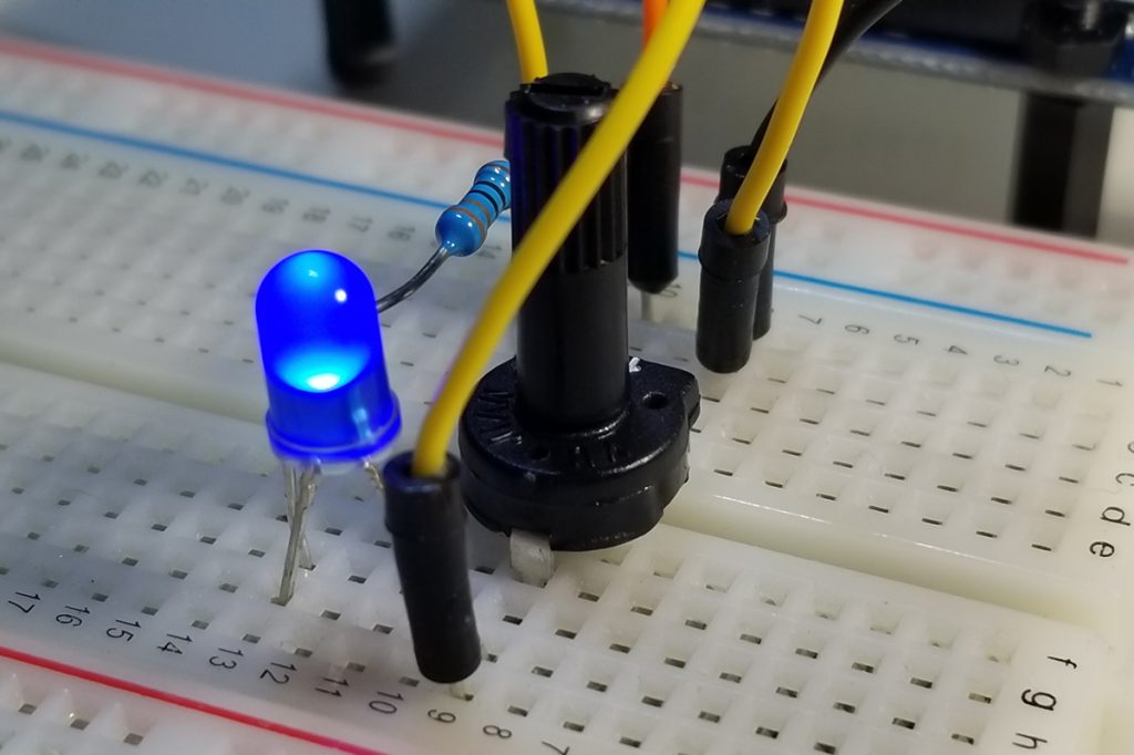
A demonstration of voltage control is demonstrated in the video below. As the wiper is rotated, the voltage level presented at the center pin of the trim pot is changed within the limits of 0VDC to the maximum voltage (5VDC). In this instance, an LED is connected to the wiper pin and its illumination level is increased or decreased as a function of voltage level.
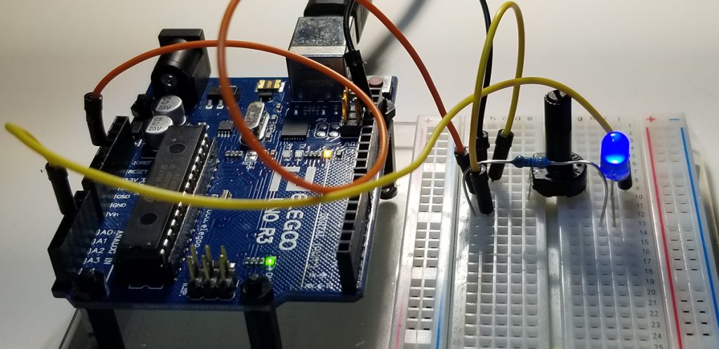
To build the circuit and operate the control, simple connections are made between an Arduino UNO and its external components as depicted below. The purpose of the Arduino is to provide the source voltage and connections for voltage level readout using the analogRead command.
Hardware Setup:
The code set up involves the configuration as written about previously in a prior post. The setups involve the three areas of interest to include variable declarations by datatype, system communication rate (9600 BAUD) between a host computer, and the Arduino’s serial monitor via the Sketch IDE. Finally, the operating code provides the instructions and commands by which operations are performed.
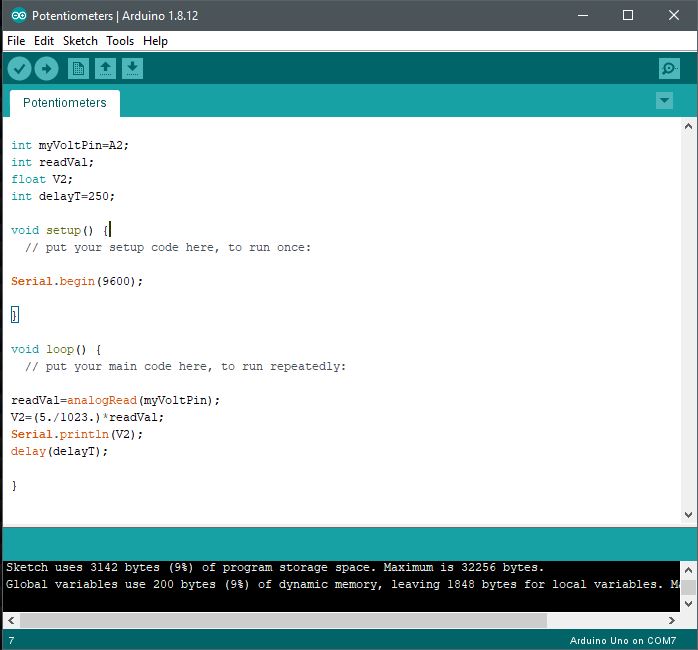
Code Setup:
int myVoltPin=A2;
int readVal;
float V2;
int delayT=250;
void setup()
{
Serial.begin(9600);
}
void loop()
{
readVal=analogRead(myVoltPin);
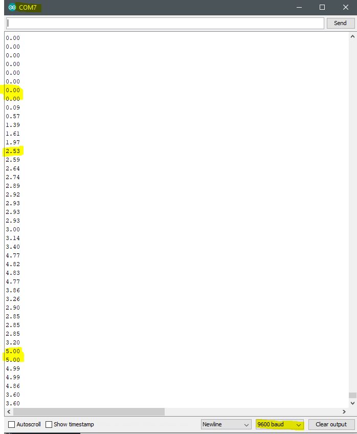
V2=(5./1023.)*readVal;
Serial.println(V2);
delay(delayT);
}
Arduino IDE:
Further Project Details: -Paul McWhorter


