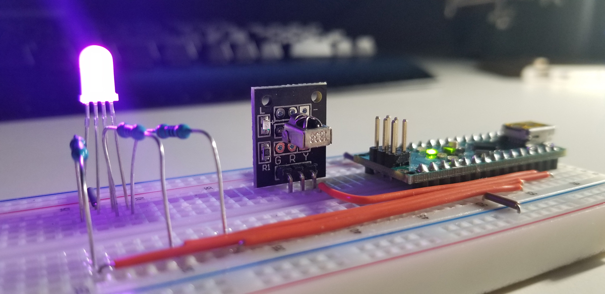
This project runs with an IR sensor that reads a remote control’s Hexadecimal data bursts as its buttons are selected. Each button represents a function that becomes executed programmatically within the Nano to affect the color and light intensity at the LED. As hex values are decoded into the Arduino Nano via the IR sensor, a conditional statement evaluates the decoded value held in memory. For each button selected, the conditional statement evaluates the hex value unique to each.
Functional Demonstration Video:
The video demonstrates a visual walkthrough of power on, off, color selection, and increase or decrease of each color brightness. Control is demonstrated through the remote control through the wireless communication made through infrared modulation of binary data decoded or translated into useful hex values for programming and operation.
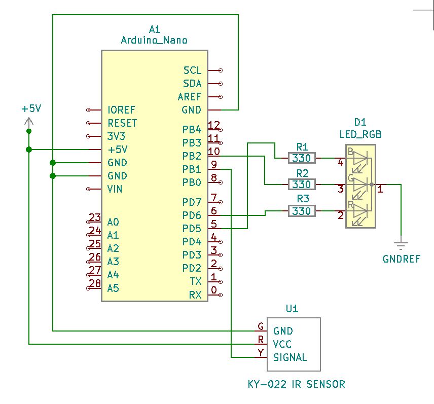
Project Schematic:
The schematic diagram of the circuit is simple. The connections are defined as illustrated as power, ground, and pin-to-pin terminations are made. The RGB LED supported with three 330-ohm current limiting resistors, but this value can be adjusted higher as desired.
Arduino IDE:
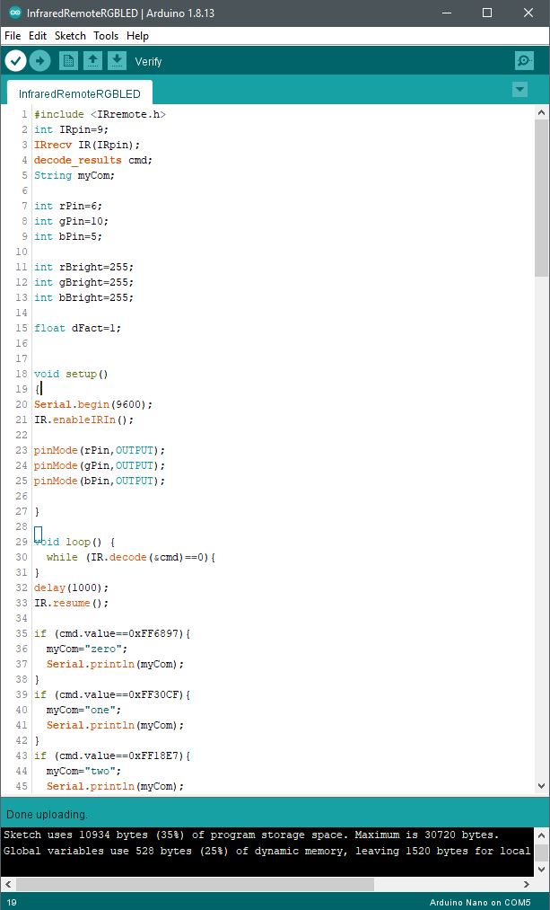
The IR sensor reads a remote control’s Hexadecimal data stream as its buttons are selected. Each button represents a function that becomes executed programmatically. As hex values are decoded into the Arduino Nano via the IR sensor, a conditional statement evaluates the decoded value held in memory. For each button selected, the conditional statement evaluates the hex value unique to each.
Code Setup:
#include <IRremote.h>
int IRpin=9;
IRrecv IR(IRpin);
decode_results cmd;
String myCom;
int rPin=6;
int gPin=10;
int bPin=5;
int rBright=255;
int gBright=255;
int bBright=255;
float dFact=1;
void setup()
{
Serial.begin(9600);
IR.enableIRIn();
pinMode(rPin,OUTPUT);
pinMode(gPin,OUTPUT);
pinMode(bPin,OUTPUT);
}
void loop() {
while (IR.decode(&cmd)==0){
}
delay(1000);
IR.resume();
if (cmd.value==0xFF6897){
myCom=”zero”;
Serial.println(myCom);
}
if (cmd.value==0xFF30CF){
myCom=”one”;
Serial.println(myCom);
}
if (cmd.value==0xFF18E7){
myCom=”two”;
Serial.println(myCom);
}
if (cmd.value==0xFF7A85){
myCom=”three”;
Serial.println(myCom);
}
if (cmd.value==0xFF10EF){
myCom=”four”;
Serial.println(myCom);
}
if (cmd.value==0xFF38C7){
myCom=”five”;
Serial.println(myCom);
}
if (cmd.value==0xFF5AA5){
myCom=”six”;
Serial.println(myCom);
}
if (cmd.value==0xFF42BD){
myCom=”seven”;
Serial.println(myCom);
}
if (cmd.value==0xFF4AB5){
myCom=”eight”;
Serial.println(myCom);
}
if (cmd.value==0xFF52AD){
myCom=”nine”;
Serial.println(myCom);
}
if (cmd.value==0xFFA25D){
myCom=”pwr”;
Serial.println(myCom);
}
if (cmd.value==0xFF629D){
myCom=”v+”;
Serial.println(myCom);
}
if (cmd.value==0xFFE21D){
myCom=”fun”;
Serial.println(myCom);
}
if (cmd.value==0xFF22DD){
myCom=”rew”;
Serial.println(myCom);
}
if (cmd.value==0xFF02FD){
myCom=”play”;
Serial.println(myCom);
}
if (cmd.value==0xFFC23D){
myCom=”ff”;
Serial.println(myCom);
}
if (cmd.value==0xFFE01F){
myCom=”dn”;
Serial.println(myCom);
}
if (cmd.value==0xFFA857){
myCom=”v-“;
Serial.println(myCom);
}
if (cmd.value==0xFF906F){
myCom=”up”;
Serial.println(myCom);
}
if (cmd.value==0xFF9867){
myCom=”eq”;
Serial.println(myCom);
}
if (cmd.value==0xFFB04F
){
myCom=”st”;
Serial.println(myCom);
}
if(myCom==”pwr”){
rBright=255;
gBright=255;
bBright=255;
dFact=1;
}
if(myCom==”fun”){
rBright=0;
gBright=0;
bBright=0;
dFact=0;
}
//white
if(myCom==”zero”){
rBright=255;
gBright=255;
bBright=255;
}
//red
if(myCom==”one”){
rBright=255;
gBright=0;
bBright=0;
}
//green
if(myCom==”two”){
rBright=0;
gBright=255;
bBright=0;
}
//blue
if(myCom==”three”){
rBright=0;
gBright=0;
bBright=255;
}
//cyan
if(myCom==”four”){
rBright=0;
gBright=255;
bBright=255;
}
//magenta
if(myCom==”five”){
rBright=255;
gBright=0;
bBright=150;
}
//yellow
if(myCom==”six”){
rBright=255;
gBright=255;
bBright=0;
}
if (myCom==”dn”){
dFact=dFact0.75; } if (myCom==”up”){ dFact=dFact1.3;
if (dFact>1){
dFact=1;
}
}
analogWrite(rPin,rBrightdFact); analogWrite(gPin,gBrightdFact);
analogWrite(bPin,bBright*dFact);
}


