This project involved a 5VDC stepper motor and its corresponding ULN2003 driver assembly. Stepper motors are unique from servos or DC motors because they are very precise, have a full range of motion, and they can produce a lot of torque. This specific motor permits 2048 steps according to its specifications, so each step represents a high level of rotational movement granularity in a small package. –The purpose of the system is to evaluate a simple stepper motor along with its driver assembly to understand their behavior, limitations, and performance characteristics.
The normally closed micro-switch provides a toggle for the stepper motor shaft to move in either a forward or reverse direction. Directionality is set by a code condition determined by the toggle switch transition states whereas the switch is depressed to activate a change of direction opposite the prior rotational motion. Programmatically, the rotational speed is set to about 10 RPM in this project, but speeds are assigned slower as desired.

Stepper motors are found among many applications today. They allow for precision movement and control of hardware throughout various industries, households, or personal devices. They open lids, doors, and windows. They drive gears to rotate lamps, sensors, cameras, and so forth. The use-cases of stepper motors are very wide-spread.

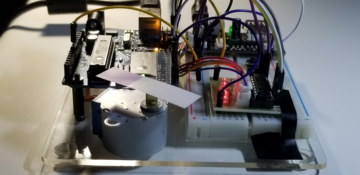
The ULN2003 IC chip located on this assembly is really an array of Darlington pairs that drive up to 500mA at 50VDC. As a current boost is produced from the second Darlington transistor staged after the first of its pair, sufficient current capacity is presented to the terminals of the assembly that hosts the ULN2003. This assembly provides for input and output connections between the stepper motor and an Arduino unit along with LEDs and voltage supply terminals.
Each LED on the ULN2003 indicates the step activity of all four stators. Notice that each stator is in a fixed position with coil wrapping. As each coil is charged on and off, the motor shaft rotates a single step.
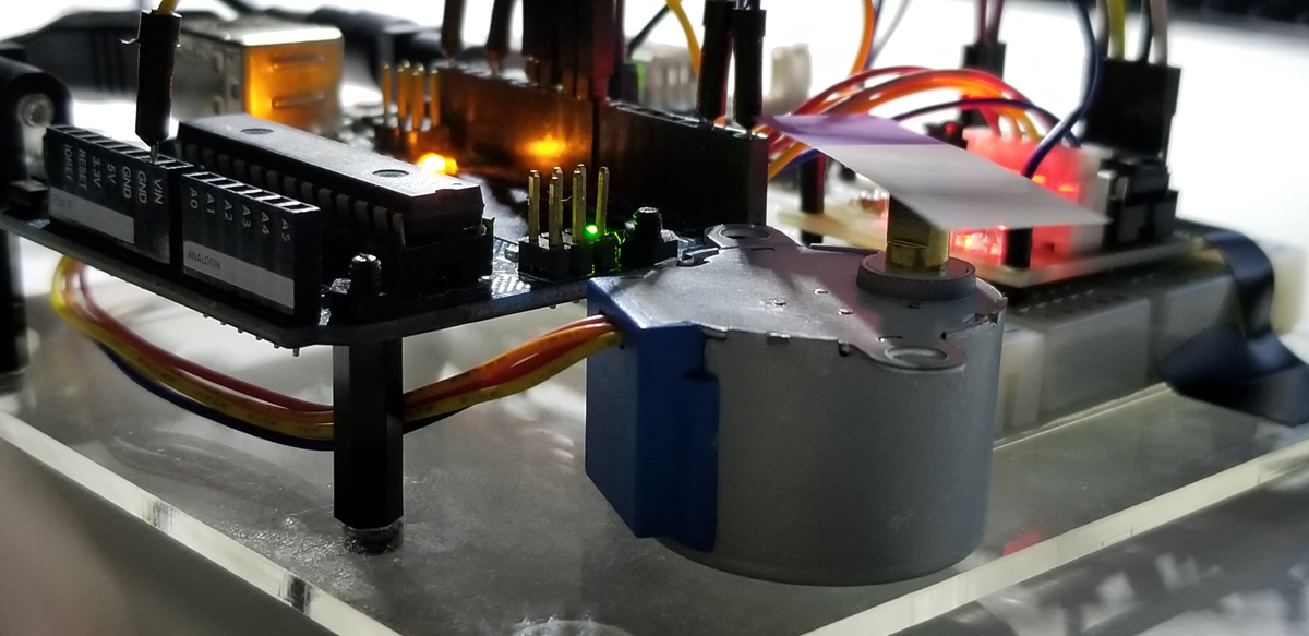
The internal workings of the stepper motor convert electrical energy (5VDC in this case) to mechanical movement. In an incremental fashion, all four coils in a fixed position advance the internal rotation in clockwise or counter-clockwise steps (depending upon motor capability). The shaft assembly that extends outside of the motor enclosure provides for a mechanical attachment to get practical use of the stepper motor.
The 28BYJ-48 stepper motor and its ULN2003 driver assembly are separately powered from the Arduino UNO R3 host. Stepper motors draw extra high current to require more power than what an Arduino can support. So this motor runs from a separate wall adapter that delivers 5VDC at 3.5A (~18W).
It is because of this higher motor current requirement that the Darlington pair boost is provided through the ULN2003 assembly. So it is necessary to recognize that motors must be matched with a corresponding driver board that includes a suitable current capacity along with the appropriate types of input and output terminations matched to the motor. Normally, stepper motors have four wires for driver connectivity.
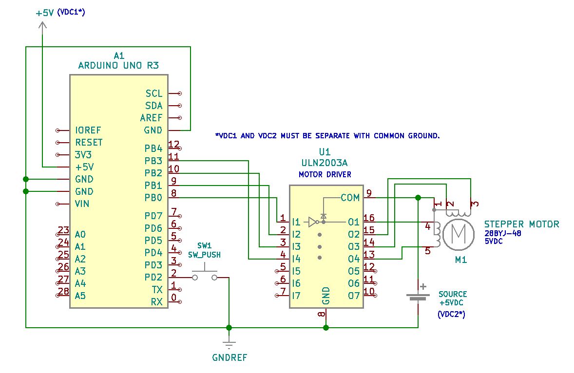
Project Schematic:
Project Review:
This video demonstrates the stepper motor’s direction of rotation as the pushbutton switch is toggled.
Arduino IDE:

Code Setup:
#include <Stepper.h>
int stepsPerRevolution=2048; //get this step count from the spec sheet
int motSpeed=10; //10 RPM
int dt=500;
int buttonPin=2;
int motDir=1; //variable to keep track direction of motor shaft
int buttonValNew; //present state of the button switch
int buttonValOld=1; //prior state of the button switch initiated as 1 (not pressed)
Stepper myStepper(stepsPerRevolution, 8,10,9,11);
//the numbers are the pin sequence for a specific driver and specific motor connected in a specific way
void setup() {
Serial.begin(9600);
myStepper.setSpeed(motSpeed);
pinMode(buttonPin,INPUT);
digitalWrite(buttonPin,HIGH); //puts a pullup high state onto the button pin
}
void loop() {
buttonValNew=digitalRead(buttonPin);
if (buttonValOld==1 && buttonValNew==0){
motDir=motDir(-1); } //button transition (1,0) sets condition for motor direction change buttonValOld=buttonValNew; myStepper.step(motDir1);
}


