To get a closer look at the analogWrite command supported by the Arduino platform, its internal pulse width modulation (PWM) function controls the duty cycle of an output voltage to drive an external circuit. More basically, you can assign argument values to the analogWrite command to affect a change in signal to an outside circuit. This is where the is a possibility of setting a discrete or continuously incremented or decremented values. Where a corresponding level is brightness intensity is observed.
int redPin=9;
int bright=127; // 0 = 0V 255 = 5VDC
void setup()
{
pinMode(redPin,OUTPUT);
}
void loop()
{
analogWrite(redPin,bright);
}
The output scale of 0 to 255 represents 256 unique values (28 = 256). Where 2 represents the two binary states 0 and 1 store in 8-bits of addressable data for registers to execute or process instructions in support 256 separate and unique values in RAM or ROM memory storage. In this case, the values selected along the scale between 0 to 255 provide increasing values of analog to digital conversion that eventually represent a full-scale value of an output voltage as a function of the available supply given to the controller.
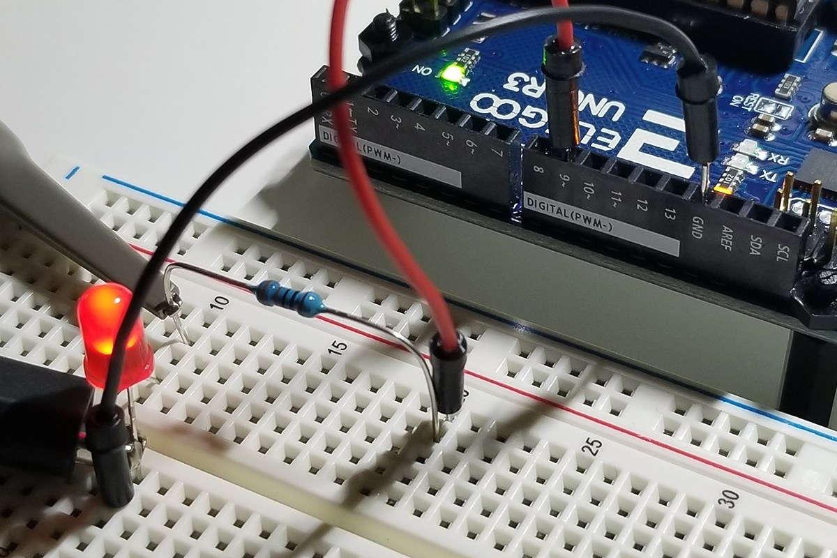
Hardware Set Up:
Notice that the pin identifiers at each suitable port with the ” ~ ” indicator supports PWM analog functionality. This is in contrast with the digitalWrite pins without the ” ~ ” symbol that does not support analog read/write operation.
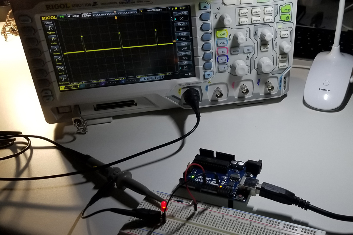
PWM Waveform Explanation:
As depicted in this diagram, the waveform is at about a 50% duty cycle with an analogWrite argument value set to 127. Peak value is at 4.960V in the measurement as indicated by the cursor, but the illumination intensity is significantly lower than full brightness because the area under each pulse is reduced by about 50% or half. The cursor and statistics data in the screen capture gives the details about the change in behavior as compared to a 255 analogWrite argument value. In such a case, the waveform would appear as a straight line on an oscilloscope for 100% of available brightness. That is full available power presented to an output circuit, which in this case is an LED.

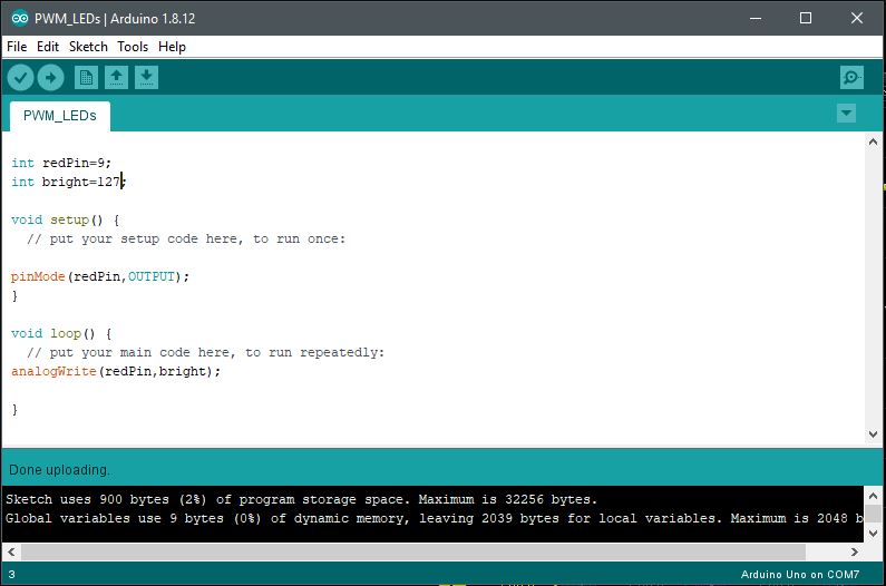
Arduino IDE:
The simple code set up within the Arduino Sketch IDE to show the details of the operation.
Further Project Details: -Paul McWhorter


Comments are closed.