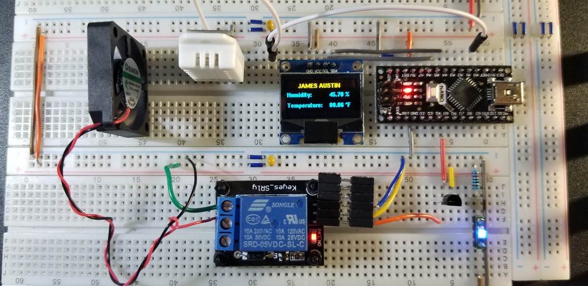
With a DHT22 (AM2302) temperature and humidity sensor, an Arduino Nano is programmed to activate a relay that in turn permits a fan that provides cooling to a designated system, or target. The relay is set up in a normally open configuration and closes the fan’s contact path to a 5VDC supply when the Arduino Nano asserts its active state. Through a 2N2222 NPN transistor, the relay is given enough signal strength from the Nano GPIO to close and run the fan. The relay’s supply does not operate from USB power, but instead, the entire system runs from its own supply with sufficient current.
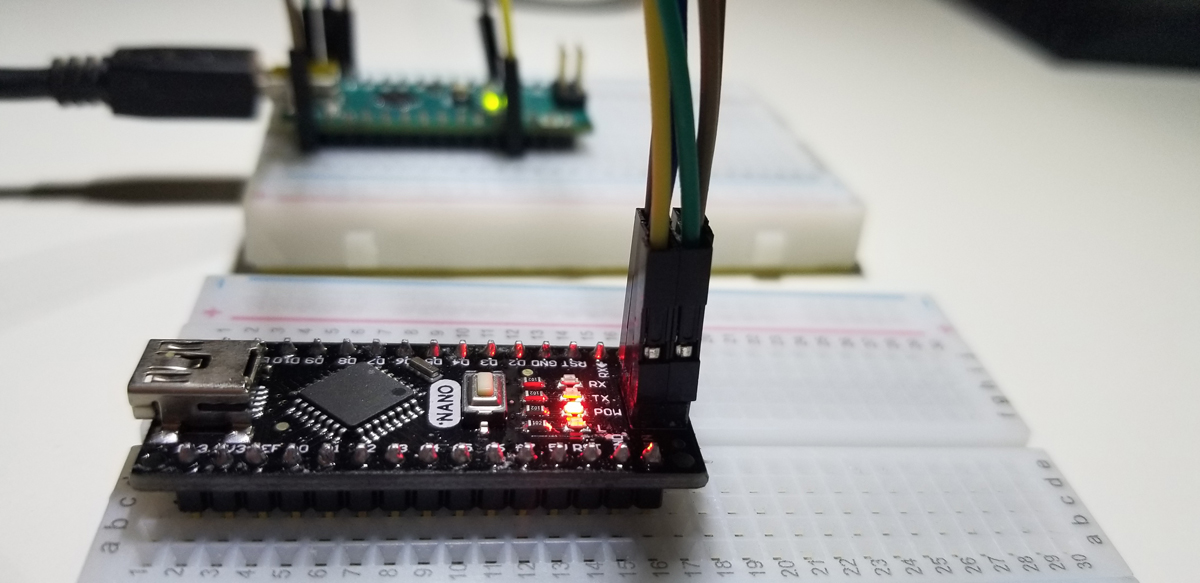
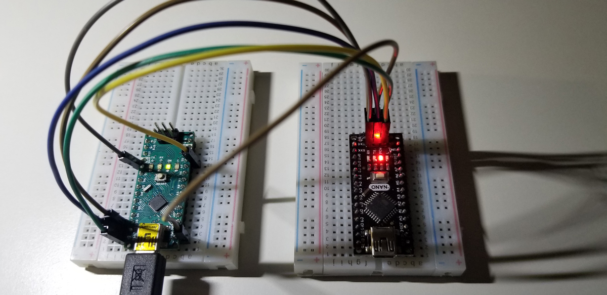
While programming the Nano, it is necessary to turn off or disconnect the primary supply to assure no adverse stresses are upon the system. Once the Nano is programmed, in this configuration, the USB plug must be disconnected to operate the primary supply for all other components (relay, fan, transistor, and sensor).
The DHT22 sensor outperforms the DHT11 sensor. Here are the differences:
- Temperature Range
- DHT11: -20 to 60℃
- DHT22: -40 to 80℃
- Temperature Accuracy
- DHT11: ±2%
- DHT22: ±0.5%
- Humidity Range
- DHT11: 5 to 95% RH
- DHT22: 0 to 100% RH
- Humidity Accuracy
- DHT11: ±5%
- DHT22: ±2%
- Cost
- DHT11: ~ $6.00
- DHT22: ~ $10.00
The DHT22 has much lower power consumption, and with a signal transmission distance of more than 20 meters. The sensor operates with a faster measurement response with less interference susceptibility.
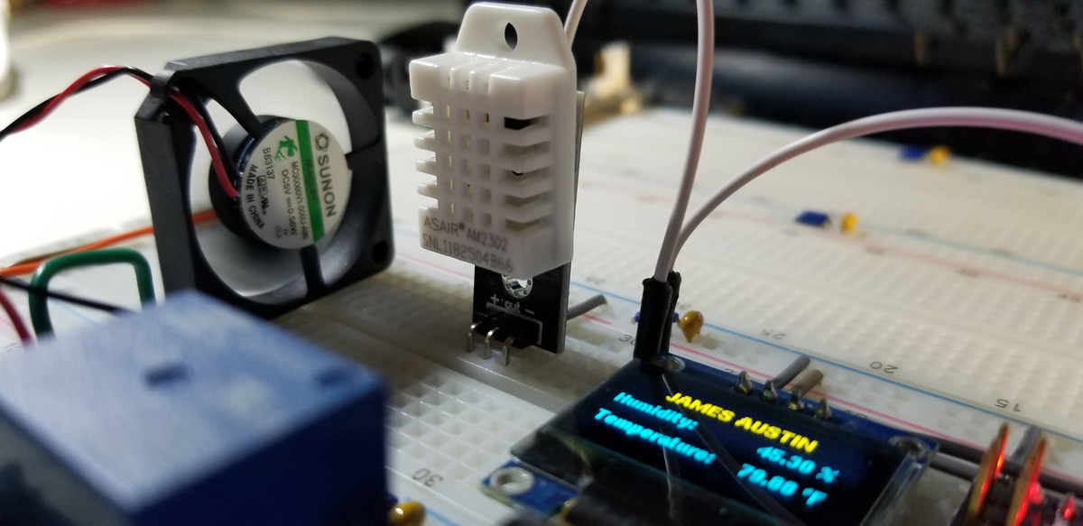
Humidity sensor of 0 to 99.9 %RH with ±2% accuracy while the temperature sensor ranges from -40 to 80℃ with ±0.5℃ accuracy.
The relay selected in this project is overkill in terms of its current capacity, but it was readily available since it has a 5VDC input operating voltage. Moreover, the Normally Closed connection isn’t used either. While this relay is a universal relay, there are many available with a lower and much more suitable rating (and cost) for this type of project.
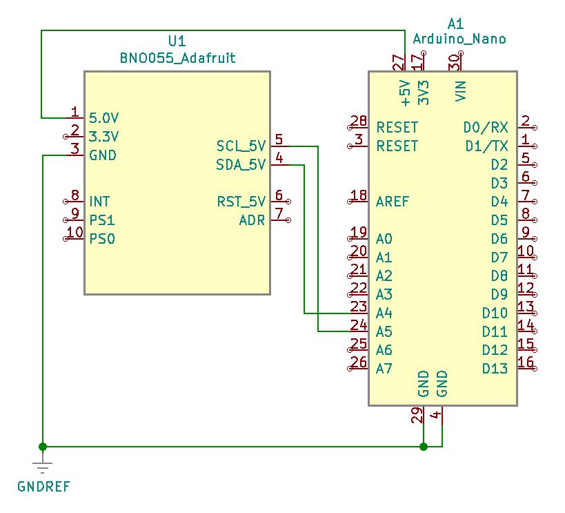
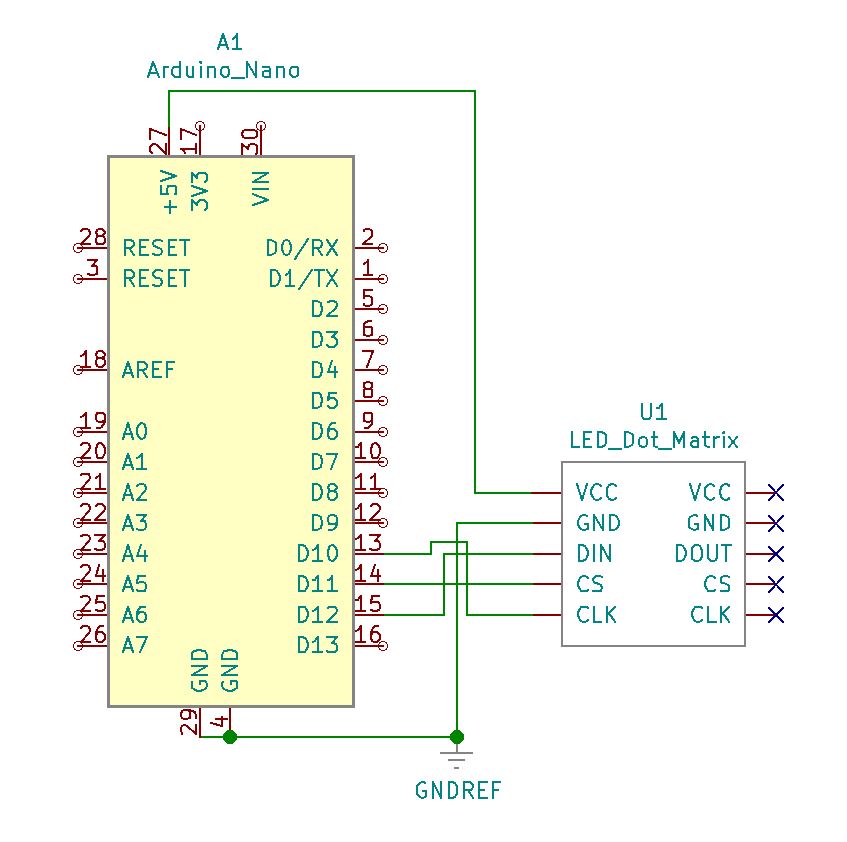
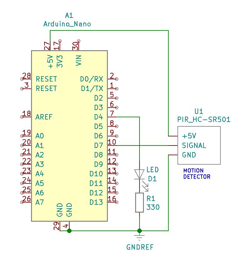
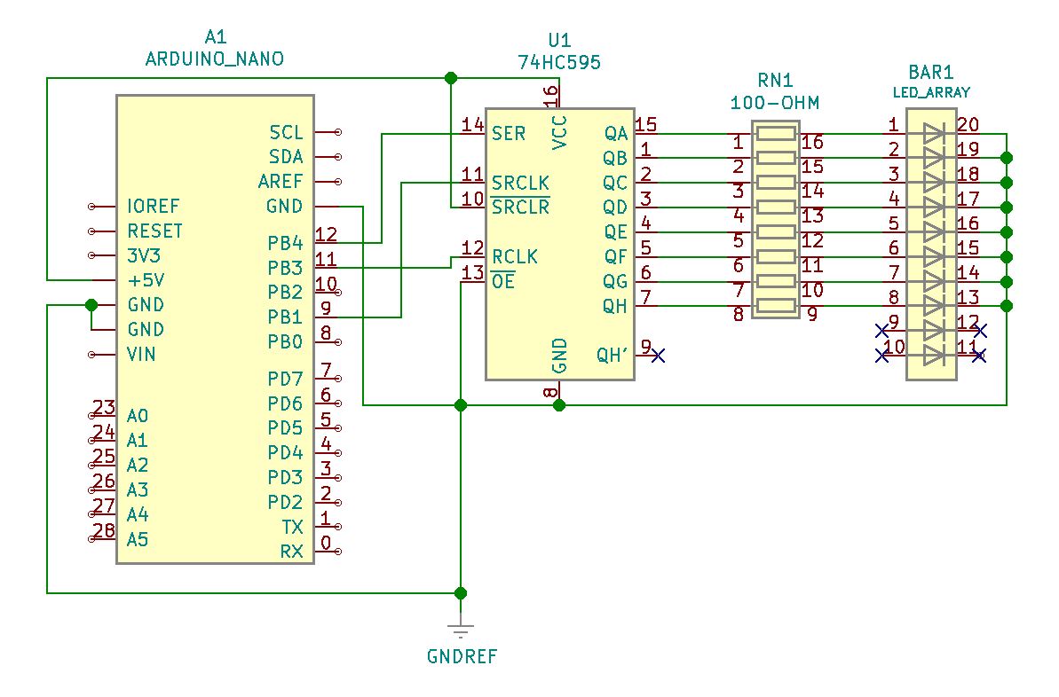
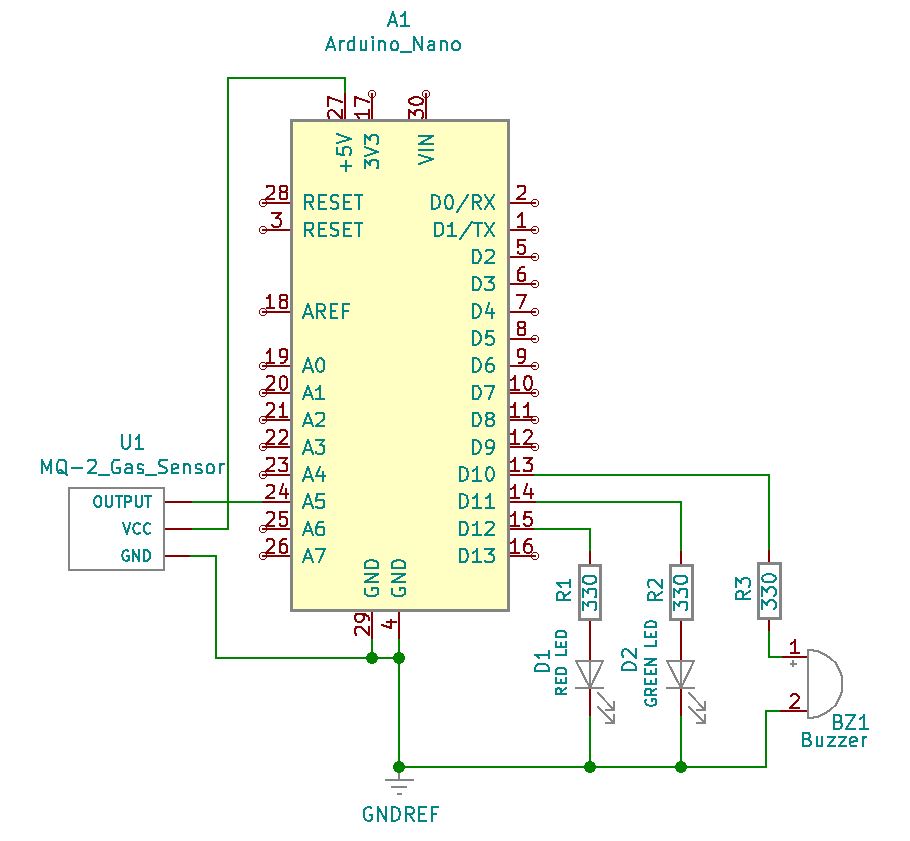
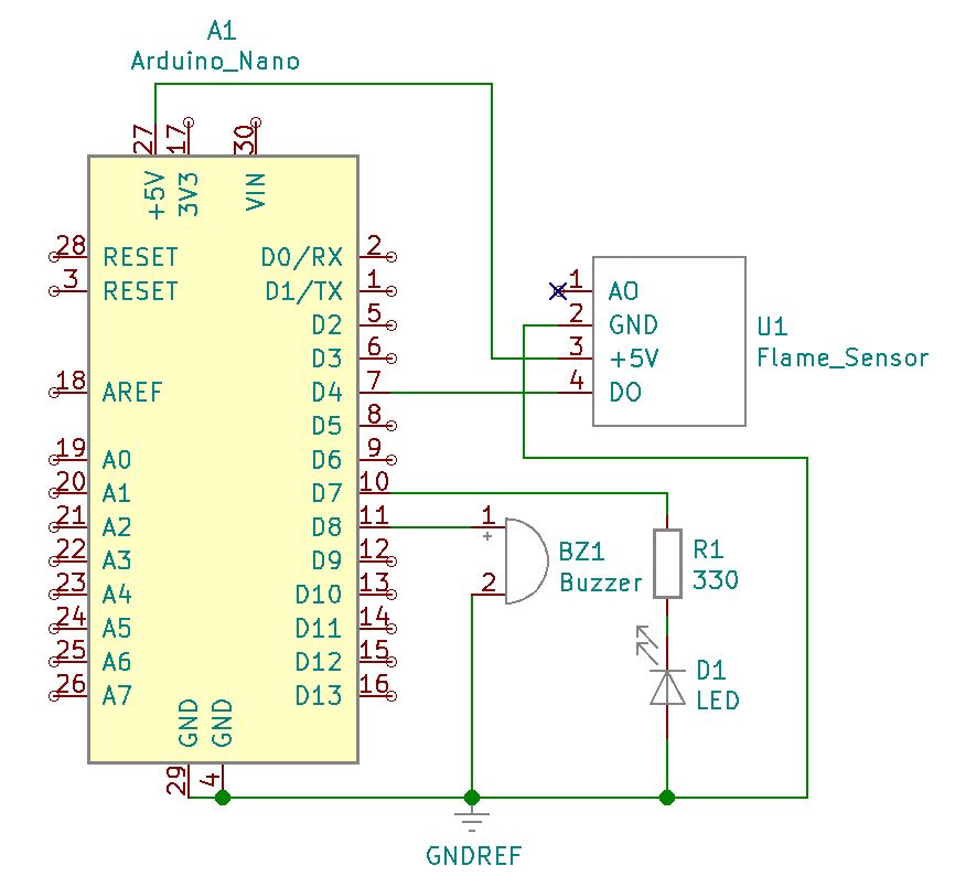
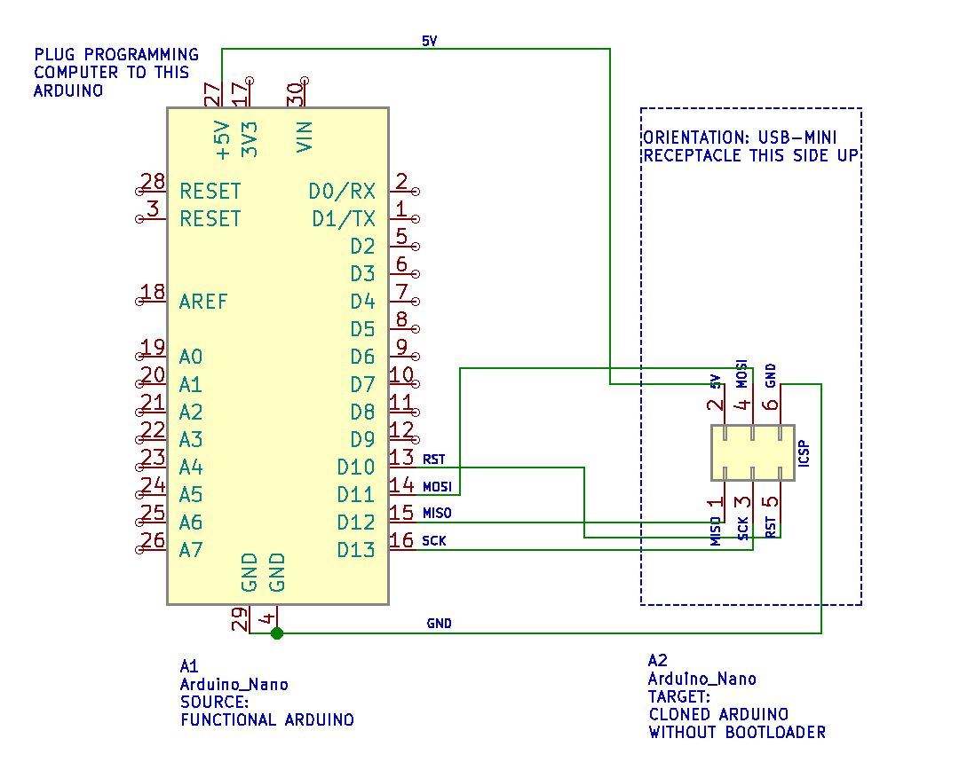
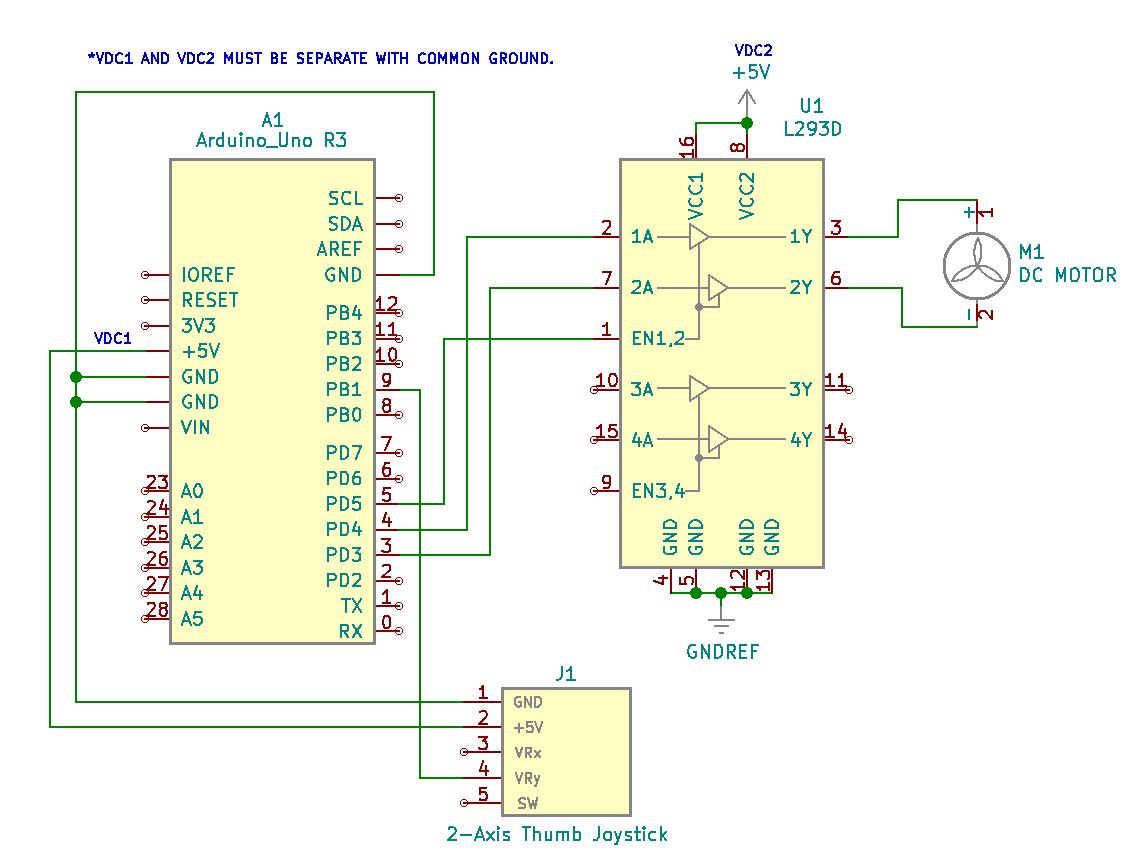
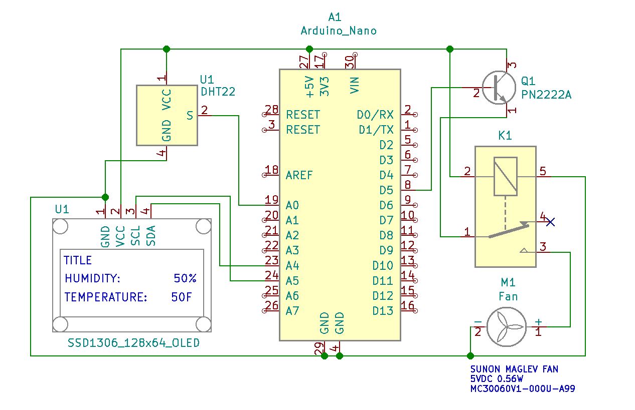
Project Schematic:
The system makes use of the SSD1306 128×64 OLED display to provide a way to monitor the DHT22 sensor’s temperature and humidity readings. Coded into the Nano is a relay and fan trigger activation point as selected. When the DHT22 sensor reads above that temperature level, the fan runs at full speed and remains that way until the temperature again decreases below the set point. If the ambient temperature present at the sensor should again rise above that trigger point, the Nano asserts an active high state and begins the fan’s operating cycle again.
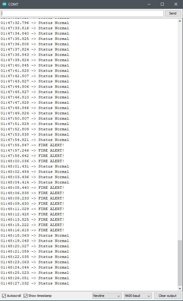
Project Review:
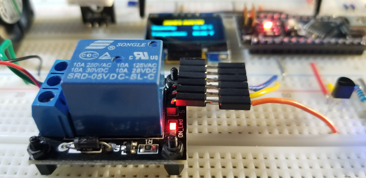
This is the demonstration to verify operation of the OLED display and the fan via the relay as the code set point is chosen at 78-degrees Fahrenheit. When the temperature drops below that point, the fan is disconnected from its 5VDC supply via the relay.
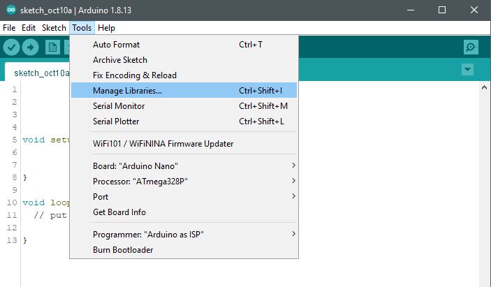
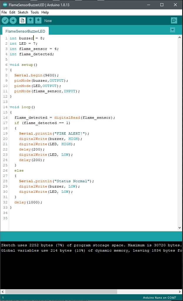
Code Example:
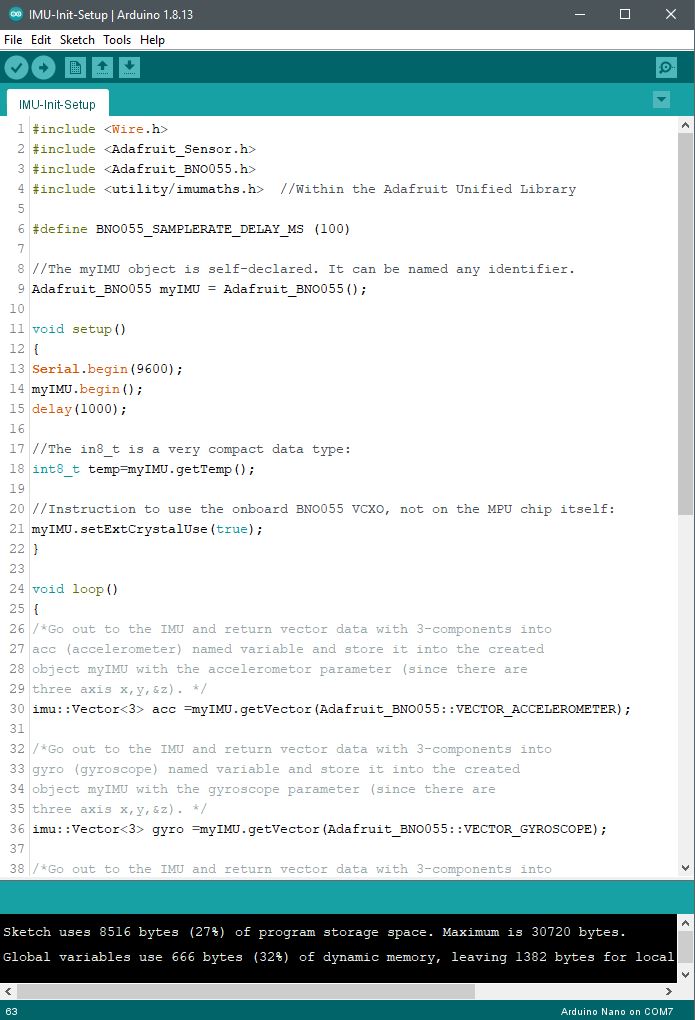
#include “DHT.h”
#include “U8glib.h”
U8GLIB_SSD1306_128X64 u8g (U8G_I2C_OPT_NONE|U8G_I2C_OPT_DEV_0);
#define DHTPIN A0 // Digital pin connected to the DHT sensor
// Uncomment whatever type you’re using
//#define DHTTYPE DHT11 // DHT 11
#define DHTTYPE DHT22 // DHT 22
char str[10];
int relay=5;
DHT dht(DHTPIN, DHTTYPE);
void setup() {
Serial.begin(9600);
Serial.println(F(“Hello James…”));
dht.begin();
u8g.firstPage();
pinMode(relay,OUTPUT);
}
void loop() {
// Wait a few seconds between measurements.
delay(3000);
// Reading temperature or humidity takes about 250 milliseconds
float h = dht.readHumidity();
// Read temperature as Celsius (the default)
//float t = dht.readTemperature()
// Read temperature as Fahrenheit
float t = dht.readTemperature()*1.8+32;
// Check if any reads failed and exit early (to try again).
if (isnan(h) || isnan(t) ) {
Serial.println(F(“Failed to read from DHT sensor.”));
return;
}
Serial.print(t);
Serial.print(“,”);
Serial.println(h);
u8g.firstPage();
do {
u8g.setFont(u8g_font_helvB08);
u8g.drawStr( 0, 15, “[ INSERT TITLE HERE ]”);
u8g.drawStr( 0, 30, “Humidity:”);
u8g.drawStr( 80, 30, dtostrf(h, 5, 2, str));
u8g.drawStr( 110, 30, “%”);
u8g.drawStr( 0, 50, “Temperature:”);
u8g.drawStr( 80, 50, dtostrf(t, 5, 2, str));
u8g.drawStr( 110, 50, “\260F”);
// u8g.drawStr( 110, 50, “\260C”);
if (t>78){
delay(25);
digitalWrite(relay,HIGH);
delay(100);
}
else
if (t<78){
delay(25);
digitalWrite(relay,LOW);
delay(100);
}
}
while( u8g.nextPage() );
}