Archive | Engineering RSS feed for this section

Toggle Switch PullUp with digitalRead

This project involves a toggle switch that an Arduino UNO recognizes through code as necessary to activate an LED over a GPIO pin. Assembly of the circuit requires a 330 resistor, 10K resistor, normally open pushbutton switch, and a red LED plus some jumpers. For added clarity about the assembly refer to the photos below. The schematic illustration merely offers a symbolic representation of the setup. The prior project involved the use of pushbutton switch that temporarily enabled an output (LED) from a GPIO pin.

This project changes the state of the GPIO (LED) each time the pushbutton is pressed. The pushbutton switch in this way operates as a toggle as a steady-state on/off through conditional instruction statements written into the code.
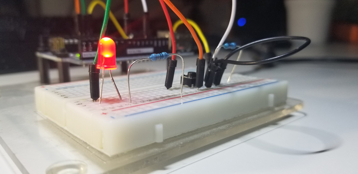
Simple set up of a small circuit to interface with the Arduino UNO R3 SBC. Includes 330 ohm, 10K ohm current limiting resistors, a RED LED, and a small pushbutton normally open switch. Circuit jumpers interface to the Arduino’s GPIO ports.
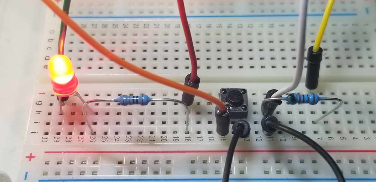
Top down view of circuit connections.

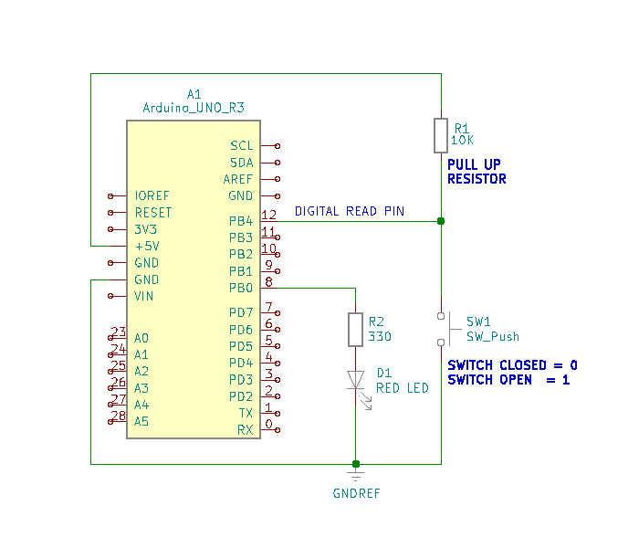
To register active high and active low states at a GPIO port, it is necessary to apply pull up or pull-down resistors to a circuit’s normally open or normally closed pushbutton switch. It is not an acceptable practice to place a GPIO pin directly to a +5V source, or Ground in order to operate a directly connected switch. The purpose of a pulldown or pullup resistor placed onto a switch is to correctly register an active high or low state at an assigned GPIO measurement pin. To illustrate the connections see the diagrams below:
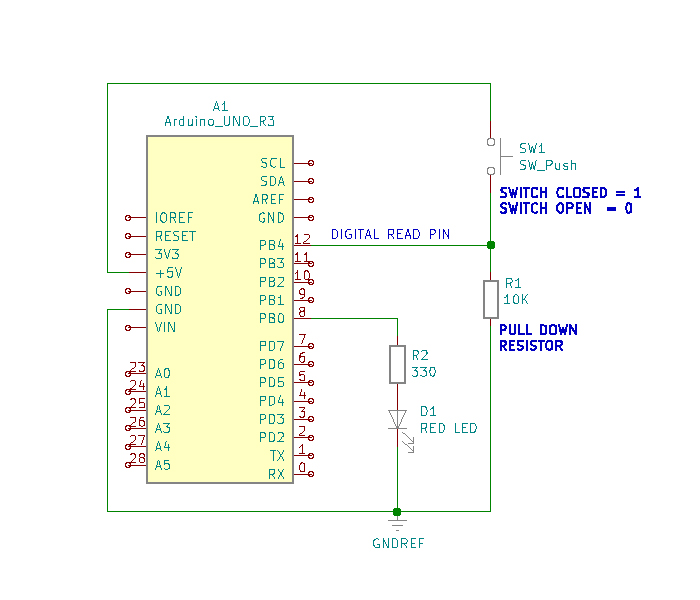
Pull Up Resistor Example
Pull Down Resistor Example

Simply put, there just must be a circuit path to either a voltage reference or ground reference using a resistor connected to a switch for proper operation. The active voltage present at pin-12, while the button switch is not pressed, is 5VDC. When the pushbutton switch is pressed this voltage level drops to 0VDC. As a 0VDC state is read into pin 12 by the digitalRead operation (i.e. pin 12 becomes grounded), pin 8 presents 5VDC to R2 for the Red LED to illuminate. While the pushbutton switch is pressed and held closed, the serial monitor presents a digital “0” state. This is due to the placement of the digitalRead command within the continuous program loop.

To run the project it is necessary to assemble the circuit onto a breadboard using the components identified above. When the hardware is set up, it is then necessary to write and run the code to get functional use of the project.


Code Setup:

int LEDState=0;
int LEDPin=8;
int buttonPin=12;
int buttonNew;
int buttonOld=1;
int dt=100;

void setup() {
// put your setup code here, to run once:
Serial.begin(9600);
pinMode(LEDPin, OUTPUT);
pinMode(buttonPin, INPUT);
}

void loop() {
buttonNew=digitalRead(buttonPin);
if(buttonOld==0 && buttonNew==1){
if(LEDState==0){
digitalWrite(LEDPin,HIGH);
LEDState=1;
}
else{
digitalWrite(LEDPin,LOW);
LEDState=0;
}
}
buttonOld=buttonNew;
delay(dt);
}

With all suitable integer variables declared, operational instructions become written to perform their intended purpose. Standard pin mode set up declarations are made, and thereafter, the main loop program begins.

The digitalRead operation is executed as the buttonPin command is asserted. The physical state change that occurs from the button switch is detected at the Arduino port (pin 12) and that change is digitally read into memory and stored to the buttonNew variable. Once a switch state is read into memory via the GPIO port, the next set of instructions act upon those states held into memory.

The if-else statement parameters check for the high or low (5VDC or 0VDC) level presented to GPIO pin 12. As the buttonOld and buttonNew variables are checked for true status against assigned states “0” to buttonOld and “1” to buttonNew, the next if-statement is executed. The LEDState is checked for a logic 0 state and if it is true, the digitalWrite command places a HIGH state (logic 1, 5VDC) to the LEDPin (pin 8) GPIO port. The LEDState is then given a logic 1 into its memory space to initialize it for repeat evaluation during the continuous loop in function. Once the true state instructions are executed within both ‘if’ commands, the program falls through the function to bypass the ‘else’ code segment and continues through to the rest to the program until completion where the loop again begins.

The second half of the conditional function, ‘else’ supports the logic evaluation that previously occurred between the buttonNew and buttonOld ‘recognized’ states. If the combination of both variable assessments proves false, the else statement becomes effective within the loop to set the LEDPin to Low. This is the equivalent of a logic evaluation that checks for voltage transitions low to high and turn the LED off. Each time this transition occurs, the program loop writes the active high to turn the LED on or off. The next low-to-high button switch transition evaluation occurs within the ‘else’ segment of the conditional loop to again set the GPIO pin to low (pin-8 LED off) if that else condition should become true.

As the program loop continuously runs, the GPIO pin accepts state changes to operate as a toggle on and off, then on and off again.


Arduino IDE:
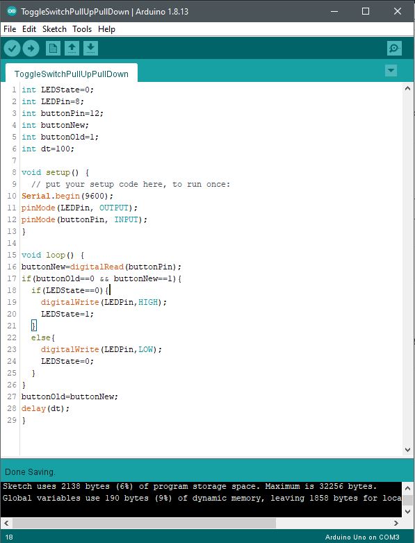
Code set up in the Arduino IDE (Sketch).

Pushbutton Switch PullUp with digitalRead

This project involves a push-button switch that an Arduino UNO recognizes through code as necessary to activate an LED over a GPIO pin. Assembly of the circuit requires a 330 resistor, 10K resistor, normally open pushbutton switch, and a red LED plus some jumpers. For added clarity about the assembly refer to the photos below. The schematic illustration merely offers a symbolic representation of the setup.

Simple set up of a small circuit to interface with the Arduino UNO R3 SBC. Includes 330 ohm, 10K ohm current limiting resistors, a RED LED, and a small pushbutton normally open switch. Circuit jumpers interface to the Arduino’s GPIO ports.
Top down view of circuit connections.

To register active high and active low states at a GPIO port, it is necessary to apply pull up or pull-down resistors to a circuit’s normally open or normally closed pushbutton switch. It is not an acceptable practice to place a GPIO pin directly to a +5V source, or Ground in order to operate a directly connected switch. The purpose of a pulldown or pullup resistor placed onto a switch is to correctly register an active high or low state at an assigned GPIO measurement pin. To illustrate the connections see the diagrams below:

Pull Up Resistor Example
Pull Down Resistor Example

Simply put, there just must be a circuit path to either a voltage reference or ground reference using a resistor connected to a switch for proper operation. The active voltage present at pin-12, while the button switch is not pressed, is 5VDC. When the pushbutton switch is pressed this voltage level drops to 0VDC. As a 0VDC state is read into pin 12 by the digitalRead operation (i.e. pin 12 becomes grounded), pin 8 presents 5VDC to R2 for the Red LED to illuminate. These states correspond to the Sketch serial monitor “0” or “1” messages presented. While leaving the pushbutton switch unpressed, the serial monitor presents a digital “1” state. While the pushbutton switch is pressed and held closed, the serial monitor presents a digital “0” state. This is due to the placement of the digitalRead command within the continuous program loop.

To run the project it is necessary to assemble the circuit onto a breadboard using the components identified above. When the hardware is set up, it is then necessary to write and run the code to get functional use of the project.


Program & Functional Operation:


Code Setup:

int LEDPin=8;
int buttonPin=12;
int buttonRead;
int dt=250;

void setup() {
// put your setup code here, to run once:
Serial.begin(9600);
pinMode(LEDPin, OUTPUT);
pinMode(buttonPin, INPUT);
}

void loop() {
// put your main code here, to run repeatedly:
buttonRead=digitalRead(buttonPin);
Serial.println(buttonRead);
delay(dt);
if(buttonRead==1){
digitalWrite(LEDPin, LOW);
}
if(buttonRead==0){
digitalWrite(LEDPin, HIGH);
}
}

Arduino IDE:
Code set up in the Arduino IDE (Sketch).

Continuously scrolled active states as values are read into memory via digitalRead from the pushbutton switch. State change from “1” to “0” to indicate LED on/off status.

Embedded System Development Environment

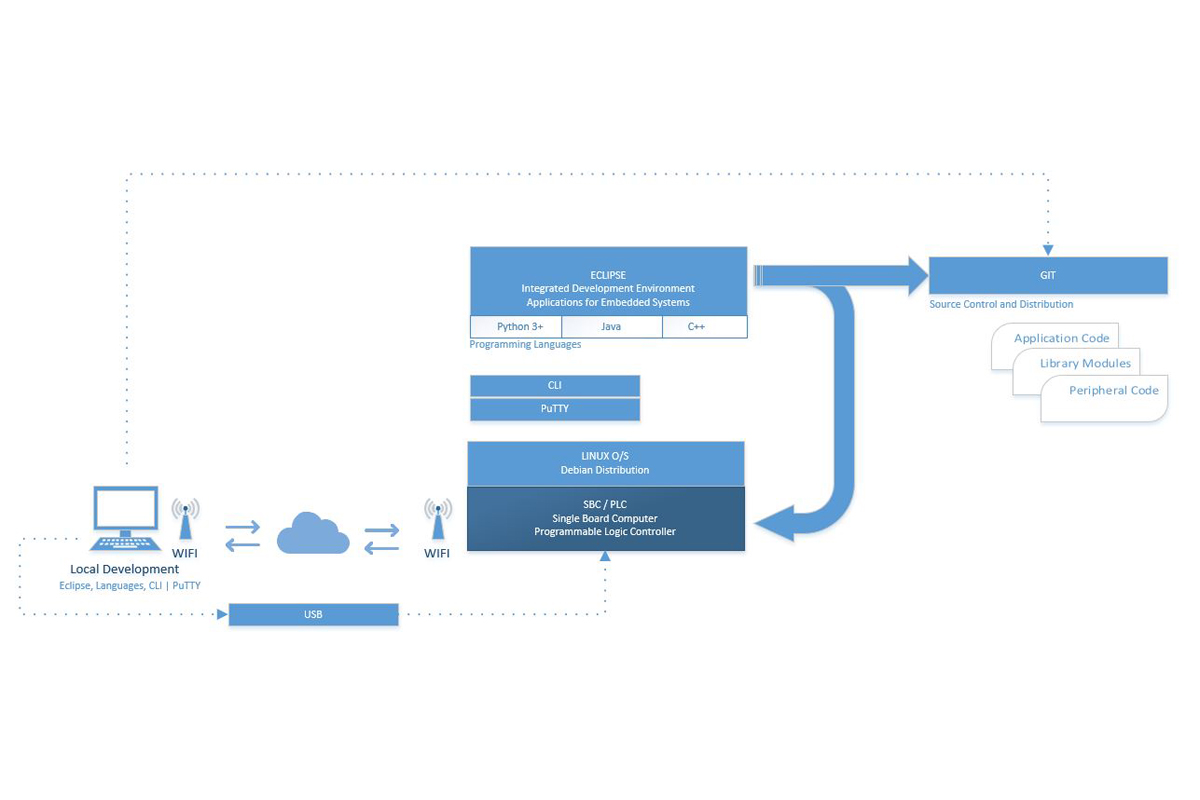
There are various tools in use that are necessary to develop hardware and software solutions involving micro-controller systems. In a practical sense, they are tools that allow a developer to design and develop the code necessary to operate and achieve a specific purpose or function. Either as a free-standing application on a single board computer or as a simple programmable logic controller solution. Application code is normally put together within a developer’s tool chest also sometimes loosely understood as a toolchain.

Wikipedia provides a write up of what a toolchain is from a software development perspective. Outlined as a sequence of utilities that include compilers, libraries, debuggers, and so on to produce an application. While completely accurate, a respective toolchain for embedded systems usually turns out different because associated hardware requirements can vary based on the platform in use. Moreover, a toolchain can look quite a bit different due to separately unique operating systems, programming languages, and development requirements at a device, component, or circuit level. A toolchain set up for an ST Microcontroller could look entirely different from a Texas Instruments or Broadcom architecture.

Embedded System Development Environment

Outlined here are typical tools that are common at an embedded system project or workstation. For professionals, makers, or hobbyists, these are common setups. Generally, from a system level, there are generally four categories and specific developer tools separated out when bringing together embedded projects of various types.

Integrated Development Environment (IDE)

This is an application that provides the framework by which code is written in a designated language for a specific purpose. Generally for embedded systems, Eclipse is commonly in use because of its support for languages generally more favorable to embedded systems. Visual Studio is also a viable choice, but there is a larger code and configuration and use overhead that accompanies VS IDE.

  • Eclipse | Site | Download (Oxygen 64-bit)
    An open-source development community with resources and tools to develop a project with a very large support base.
  • Visual Studio | Download
    Microsoft’s developer community provides open-source support through its free Community developer IDE.

Languages

These are merely a few languages that are possible to implement for an embedded project. They are outlined here because they are highly common as tools among thousands of developers.

  • Python | Download  (Windows) | Download (Mac) | Download (Linux)
    “Python is an interpreted, interactive, object-oriented programming language. It incorporates modules, exceptions, dynamic typing, very high-level dynamic data types, and classes. Python combines remarkable power with very clear syntax. It has interfaces to many system calls and libraries, as well as to various window systems, and is extensible in C or C++. It is also usable as an extension language for applications that need a programmable interface. Finally, Python is portable: it runs on many Unix variants, on the Mac, and on Windows 2000 and later.” Source: General Python FAQ.
  • C/C++
    Compiler language normally installed during IDE set up. For example, when a developer installs Eclipse, or Visual Studio, C/C++ and Python extension support is selected to immediately start programming, test, and debug in the desired syntax or language.
  • Java
    A general-purpose object-oriented programming language. Also normally an extension to an IDE installation. An often popular choice of developers of embedded systems.

Utilities

Single-board computers with firmware code embedded within a micro-controller, flash or memory, are typically supported by a Linux O/S. A Linux distribution is commonly specific for embedded systems such as Debian.

  • Linux | Download (Debian)
    A free version of Linux that supports application software to accomplish various tasks at a user-level. It comes with about 51,000 packages of free pre-compiled software to run on top of Linux to support what programs a developer might produce within a chosen programming language. The distribution is relatively light with a total size of about 2GB.
  • Notepad | Download (Notepad++)
    A free source code editor and note pad application as a straight-forward text editor. Very useful as a scratchpad, or an easy-to-use program editor that doesn’t operate as an IDE.
  • PuTTY | Download
    An SSH and telnet client developed for Windows. PuTTY is open-source software. A free and open-source terminal emulator, serial console, and network file transfer application. It supports several network protocols, including SCP, SSH, Telnet, rlogin, and raw socket connection to gain access to an SBC or controller device over a network.

Support

  • GitHub | Site
    Another software development platform, but largely used for source control and code sharing among teams, privately or publicly. Very useful to commit to a repository as code advances and development continues. Multiple concurrent code instances and versions are supported across projects for more organized and effective development.

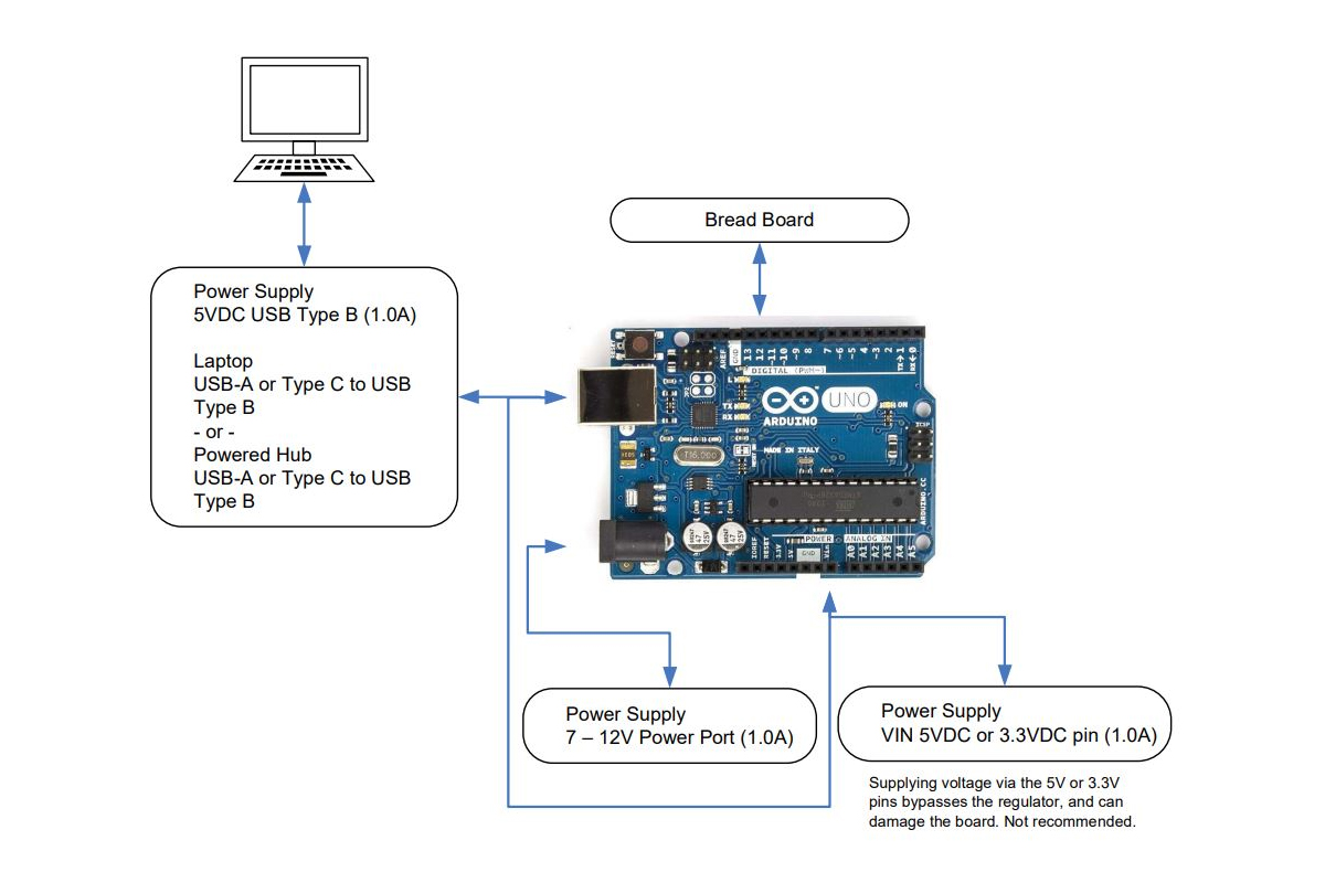
Arduino Uno Set-Up

As previously posted with the RPi set up, the same is illustrated here but for Arduino Uno. A very common single board computer that is entry level and simple to set up and operate

As before, three areas of interest are given.

Block Diagram
Pin Out Diagram
Tool Chain

The purpose of each work together to build hardware and software controller applications that operate with a host or in a freestanding manner.

While Arduino is widely understood as an entry-level SBC, it can be found among enthusiasts, makers, and project minded people who wish to build projects and code them for unique applications. Centered on the ATMega microcontroller, the software support is deep in a large community of developers. The development environment is an IDE appropriately named Sketch.

Arduino Uno Hook-up Diagram
Continue Reading →

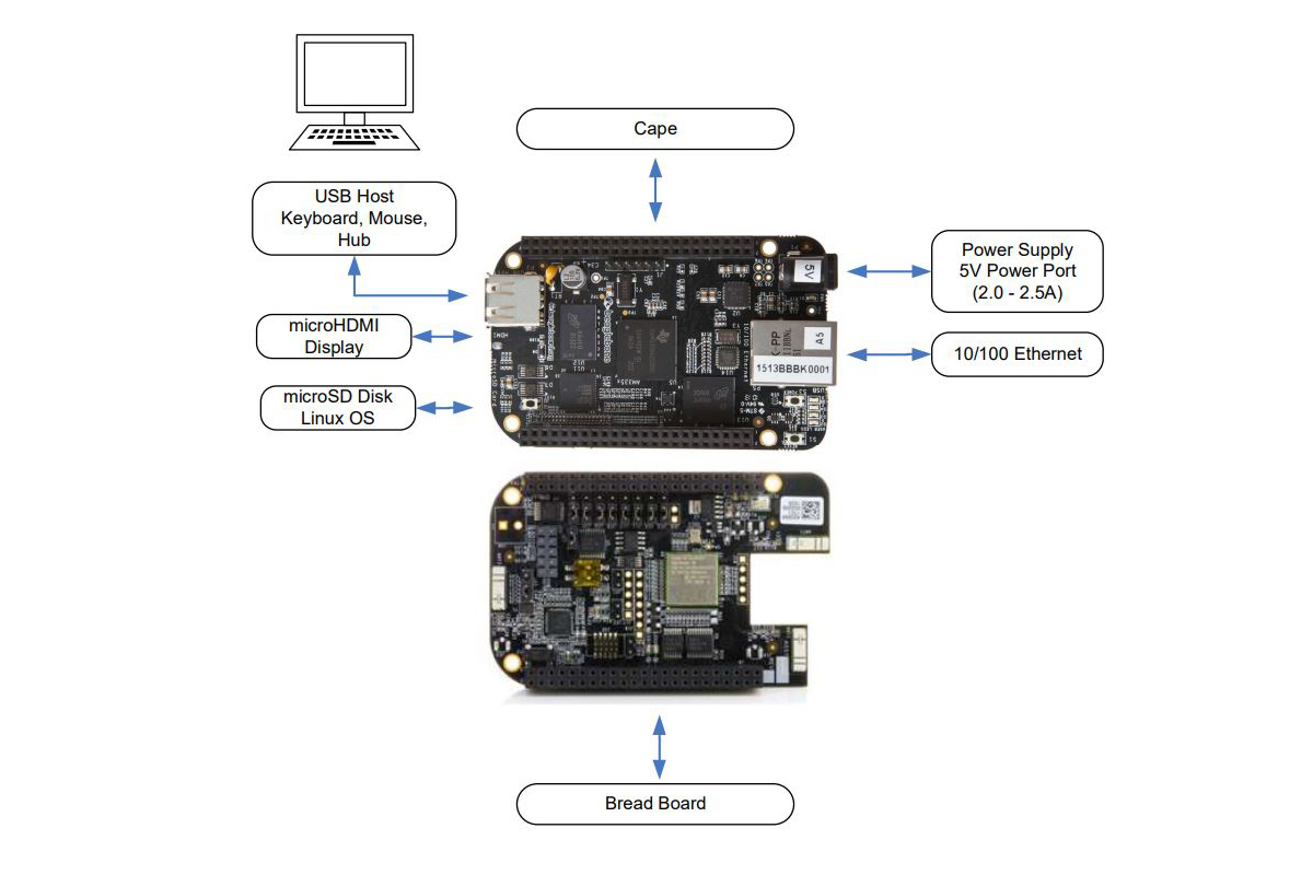
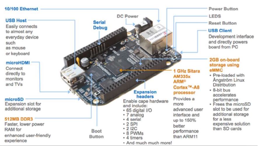
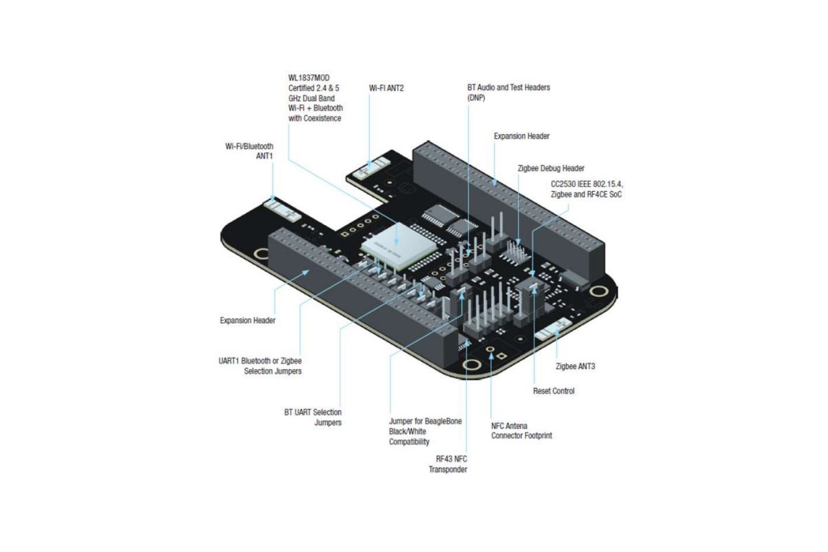
Beaglebone Black Set-Up

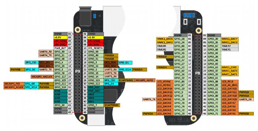
This is the third set up posting for an SBC system. This time it is for the Beagle Bone Black with a wireless cape. The attached PDF and diagrams posted here provide a suitable reference for a project in terms of hardware and software development. While there are a number of illustrations and diagrams of interest here, there is also an excellent text by Derek Molloy that offers a more comprehensive look at the setups to support projects of numerous types (ISBN 978-1118935125).

As previously posted with the RPi and Arduino Uno setups, the same is illustrated here but for BeagleBone Black. A very common single-board computer that is entry-level and simple to set up and operate. Widely known among makers, academics, and students for control automation, robotics, and sensor/actuator processing applications.

Beaglebone Black Hook-up Diagram
Beaglebone Black Pinout Diagram
Beaglebone Black Functional Diagram
Beaglebone Black Cape Functional Diagram

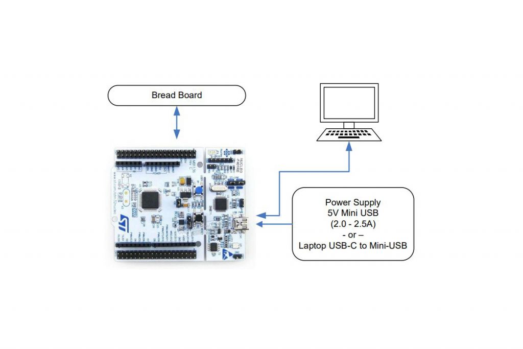
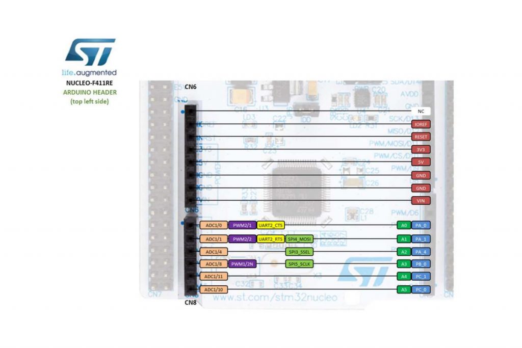
ST Micro Nucleo Set-Up

The ST Micro Nucleo single-board computer (SBC) provides for both analog and digital ports that offer more flexibility toward projects developed. In terms of its physical hardware set up, it is probably the easiest to bring together as compared to other more common SBC solutions.

The Nucleo board is supported by the mbed development system. An online code editor to produce applications for a wide range or project types. The SBC largely provides for a USB interface, power, clock and general purpose I/O in a small form factor.

It can operate with a host or as a freestanding board for set and forget applications. Largely to compete with Arduino, but also for development support of STMicro controller ICs which involve evaluation, qualification for suitability, etc.

ST Micro Nucleo Hook-up Diagram
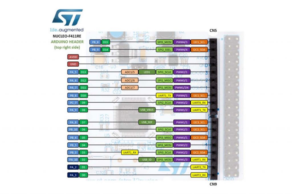
ST Micro Nucleo Pinout Diagram 1
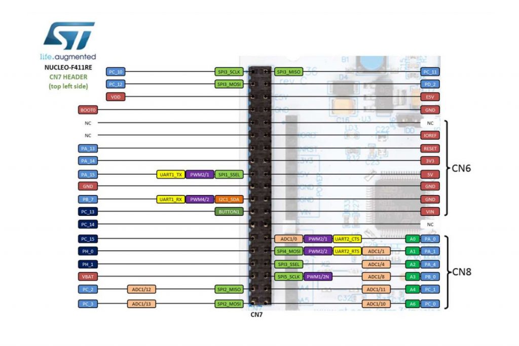
ST Micro Nucleo Pinout Diagram 2
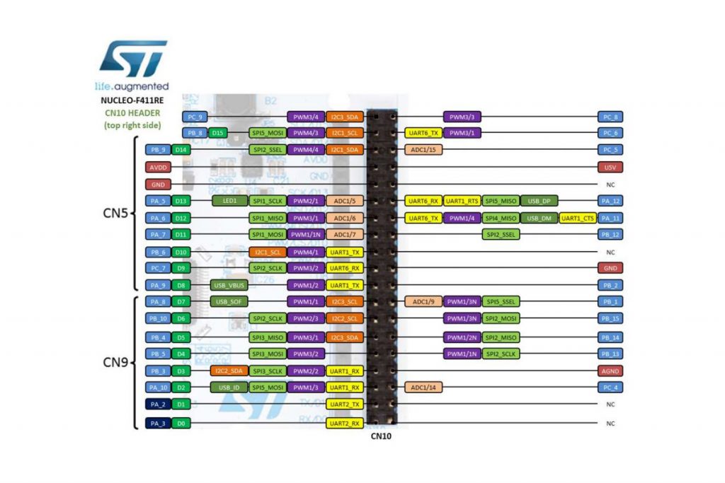
ST Micro Nucleo Pinout Diagram 3
ST Micro Nucleo Pinout Diagram 4

Raspberry Pi Set-Up

As a way to set a reference about how Raspberry Pi gets set up for repeated and continued use, it makes sense to identify system components in one place. Altogether for ease of use and assembly. This diagram is a way to identify hardware and possible software elements for development and exploration.

More specifically, a block diagram is illustrated to indicate where various interfaces apply. Display ports, power, general-purpose I/O, USB, and so on. Since peripheral connectivity is quite large with the 40-pin dual inline connector, a pin-out diagram is also illustrated here. Each pin having its reference number and name to describe its purpose.

Continue Reading →

Photoresistor Sensor Control of Buzzer Alarm

Using the point-slope formula between the on-time and off-time of a passive buzzer, we can control the high frequency and low-frequency tone sound as a function of light. As a light source is drawn near to the photoresistor, the buzzer will increase in frequency. Conversely, as the light source is moved away from the photoresistor sensor, the buzzer sound will correspond to a low-frequency tone. Removal of the light source fully separated from the photoresistor permits an ambient light reading until the buzzer is fully settled to a maximally lower frequency of sound.

By experimenting with the point-slope formula in the code, you are able to change the tonality. However, to get a precise range and audible quality of the buzzer, it is best to calculate the on-time from a sample source reading at the sensor and an off-time (delay time) to complete each frequency cycle. The more cycles of on and off time, the higher the frequency.

Simple component placement and wiring hook up.

5K Resistor in series with the photoresistor sensor. The Arduino UNO pin connected between the 5K resistor and the light sensor is reading a change in voltage present at this connection. The voltage divider changes value as the resistance of the light sensor increases or decreases. As the sensor’s resistance value decreases with increasing light levels, it conducts more and drops less voltage. The analogRead code instruction detects the change of voltage at this node and in turn produces change in tonality via the digitalWrite command at the output pin connected to the buzzer.

5K-ohm resistor in series with the photoresistor sensor and passive buzzer.

This is a passive buzzer that is driven by a voltage and light level separated by a delay between each digitalWrite event. Causing the buzzer to produce a tone of lower or greater frequency as new voltages are presented to it. Each new voltage level from the voltage divider produces its sound frequency by continuously turning the buzzer on and off again as it recognizes new levels as light intensity changes.

Light Sensor and resistor voltage divider input source. With separate buzzer output termination, the Arduino UNO module serves as the processing device for control via code instructions. ( Negative polarity terminal disconnected to interrupt operation).

Program & Functional Operation

This video demonstrates a change in buzzer tone as the light source distance from the light sensor is changed. The closer to the light sensor is exposed to a higher intensity of illumination, the higher the frequency in sound. The lower the light intensity, the lower the sound pitch or frequency.


Light & Delay Value Selection

To come up with a delay value for the integer variable declared in the code, it is necessary to the light sensor’s voltage value into memory via pin A0 on the Arduino. This means it is necessary to perform a calculation on the changes of input voltage levels as they change as light illumination intensity changes. The formula derivation is as follows:

-Paul McWhorter

Code Setup:

Copy & paste this code to your Arduino Sketch as desired to edit or experiment with your program.

int lightPin=A0;
int buzzPin=8;
int lightVal;
int delayT;

void setup()

{
pinMode(A0,INPUT);
pinMode(buzzPin,OUTPUT);
Serial.begin(9600);
}

void loop()
{
lightVal=analogRead(lightPin);

//This sets the tone for the buzzer
delayT=(9./550.)lightVal-(9.200./550.)+1.;

Serial.println(delayT);
digitalWrite(buzzPin,HIGH);
delay(delayT);
digitalWrite(buzzPin,LOW);
delay(delayT);

}

Arduino IDE:

MatPltLib, OpenCV, Numpy, Visual Studio IDE, & Python

There are numerous configuration requirements involved in the setup and operation of the Jetson unit to produce relevant AI related projects. To support meaningful project activity, these are the steps to go through. Much of this effort

  • Install and update Linux
  • Install Visual Studio Code IDE
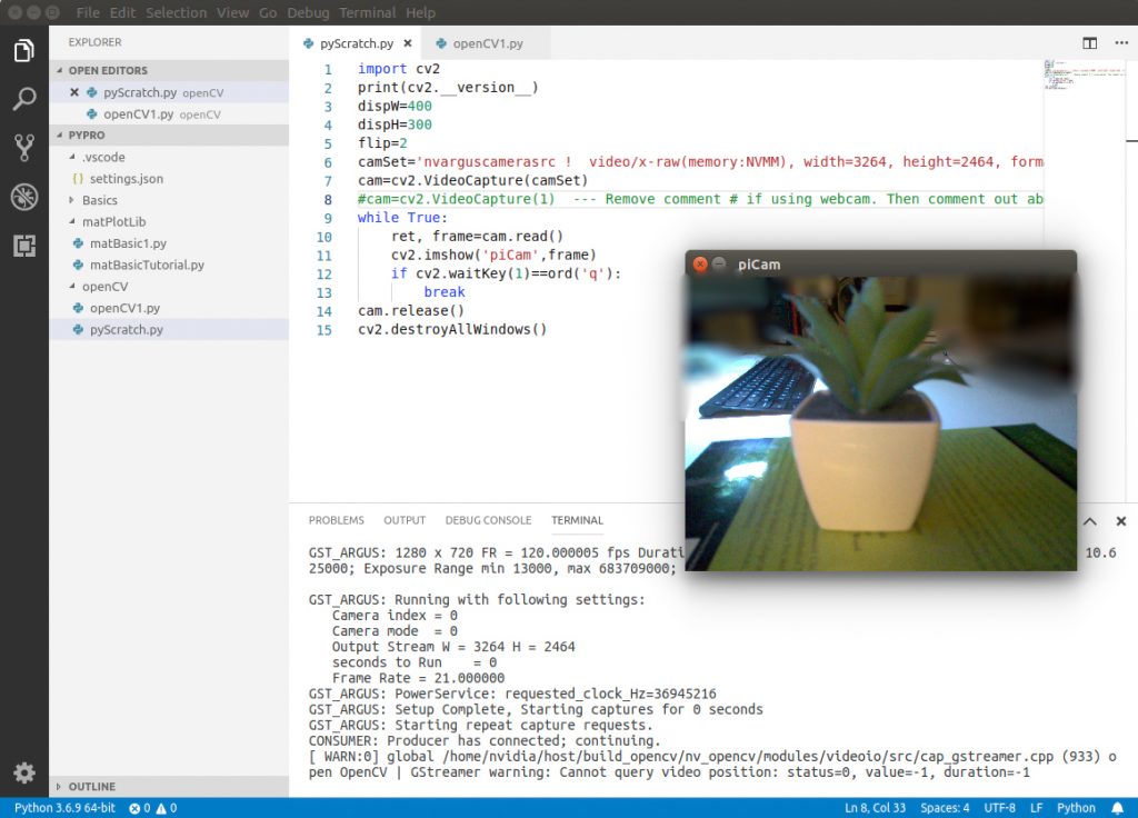
  • Install Python 3 using VS Code IDE
  • Install Code Interpreter
  • Install and update openCV library for AI applications
  • Install Numpy library for numerical function support
  • Install MatPltLib to plot mathematical operations and arrays

Upon completion of the setup walk-through, the short initialization program is necessary to get the camera operating. This initialization code adds libraries and configures the camera with settings unique to its resolution limits or parameters.

Rear port view of Jetson Nano prepared for updates.
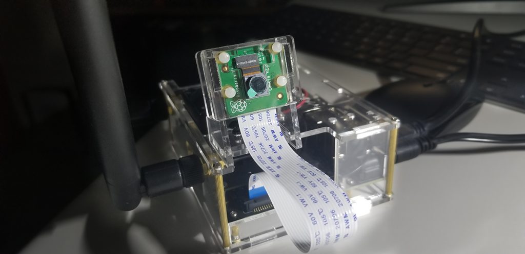
Front view of Jetson with RPi camera module. It is also possible to run a USB webcam as well.
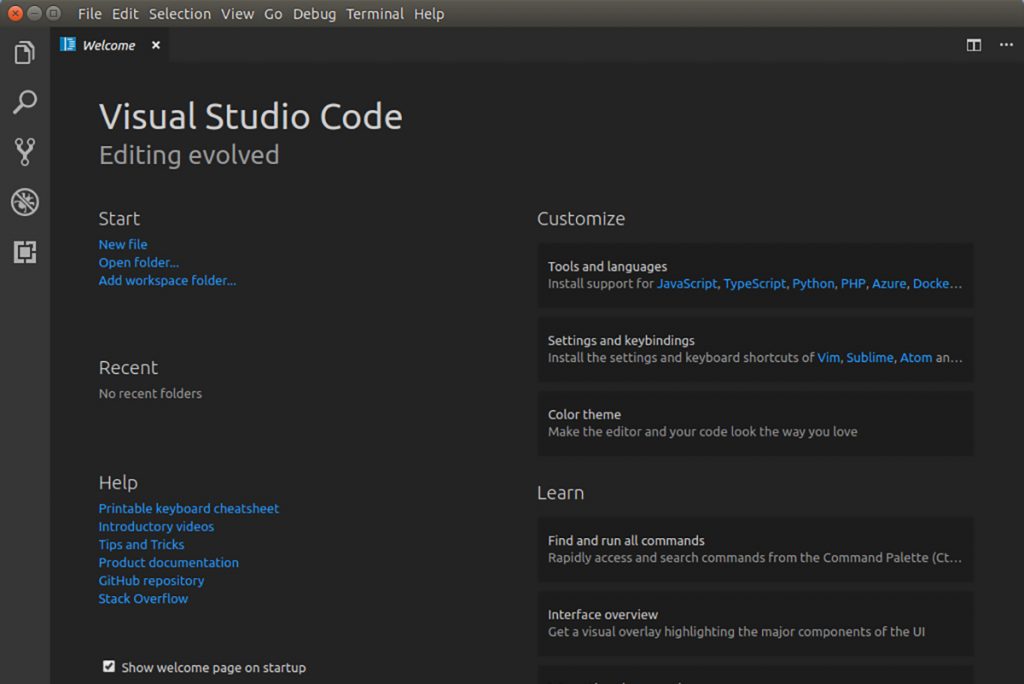
Visual Studio Code Integrated Development Environment (IDE). A host environment to support code languages such as Python.
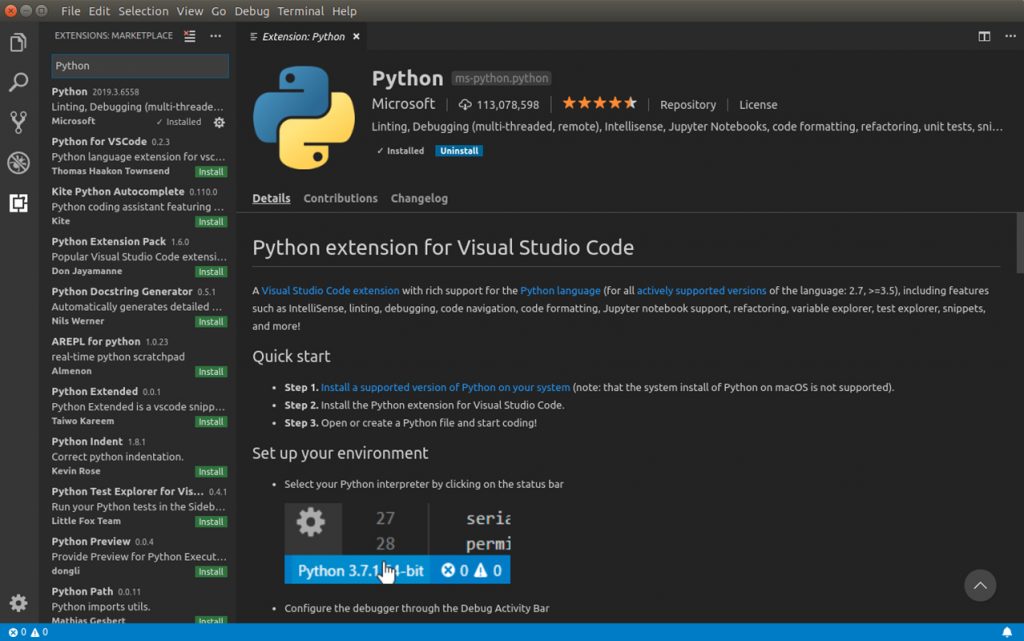
Python 3 installation, confirmation to indicate version and readiness. After installation it is necessary to install the interpreter that runs beneath Python.
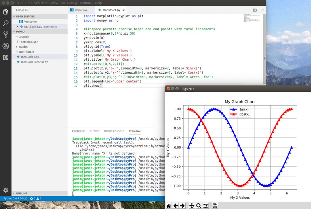
Once MatPltLib and Numpy is installed, sine and cosine functions are run as separate plots graphed. Or linear data is run as x and y array variables from memory. Simply to test and observe the numerical operation support along with the plotting utility.
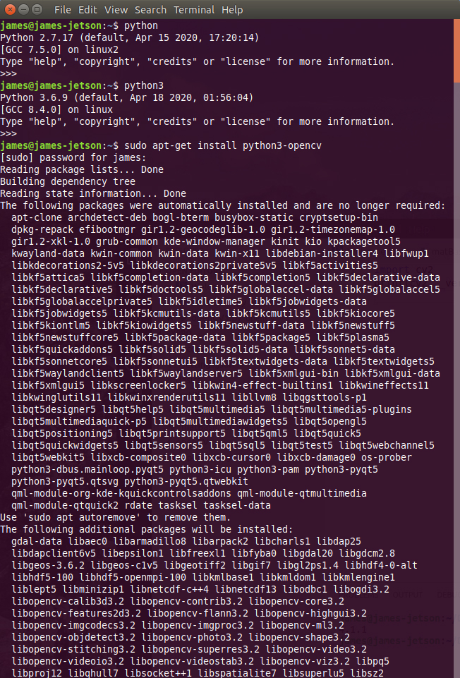
Once openCV is installed and updated from the Linux terminal, set up and configuration is required to begin operating the Jetson unit and camera to support tracking and overlay for objection detection and computation.
Installation command and activity to install openCV. To update openCV it is necessary to remove the latest installed package version using the sudo apt-get remove python3-openCV.

Python Function Review for Jetson Nano Projects Pt.2

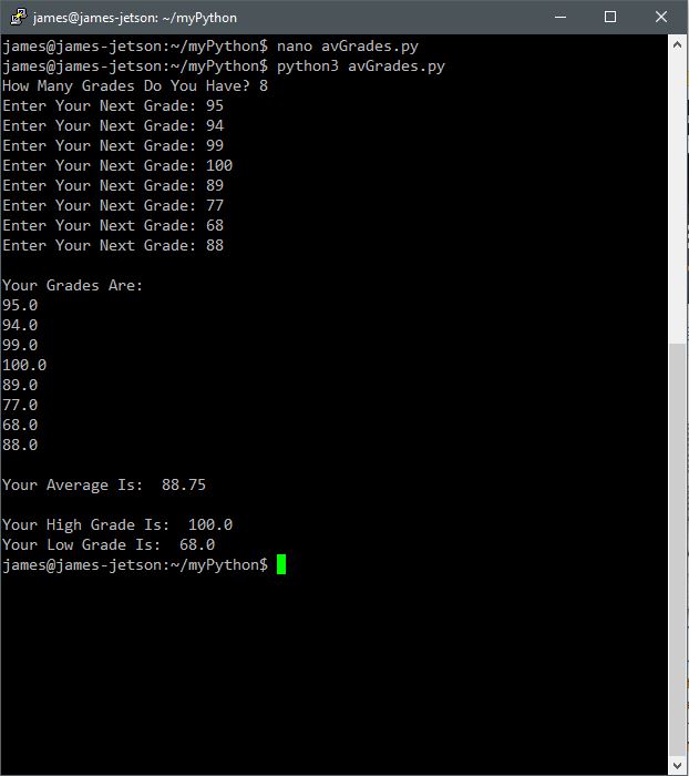
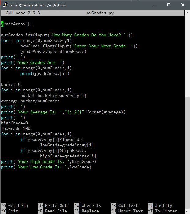
A separate walk through of how the prior session involved arrays and conditional loops is completed here only this time in headless mode. The objective of this session was to extend the function by assembling the logic and method by which grades are collected by user input and averaged for display as an output to a user. The screen captures below indicate the specific code and Python executable. The video provides for a more complete view of the session.

Python 3 code written in the Linux nano utility. A common old-school text editor to produce the code for Python to run the program.
Operating results of the Average Grades program written to collect, average, and display grades.
Video walk through to indicate both the code and executable.

Active Level Alarm with Trim Control via GPIO

This project sets up a continuously monitored voltage level change at a potentiometer as derived from a source reference. As continuously variable voltage level changes, voltage levels are read into memory from an analogRead operation. From memory, those levels are read and compared to an assigned maximum value (1000). If an increase of voltage is exceeded beyond that value (by potentiometer control), the alarm triggers with a corresponding notice within the serial monitor.

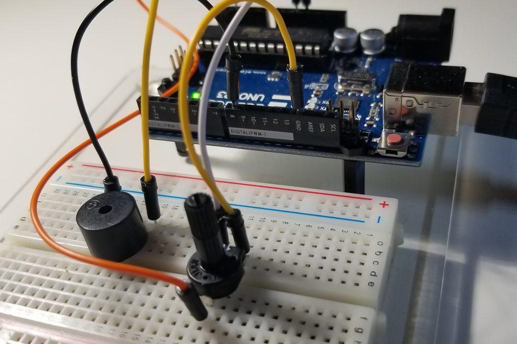
Active buzzer and potentiometer connectivity to Arduino UNO. Analog GPIO pin A3 and digital GPIO pin 8 attached to potentiometer and DC buzzer respectively. This is no a passive buzzer which requires and AC signal.
Both devices require a ground path while only the potentiometer requires its reference 5VDC. The wiper pin of the pot is connected to the A3 GPIO port.

Program & Functional Operation:

This video demonstrates how the code corresponds to the running levels that appear at the Serial Monitor. Notice the code specifies a 1000 limit to the analogRead of the potentiometer level value. Further along in the video, the potentiometer control is rotated to indicate an exceeded level until rotated back below that value again.


Code Setup:

int potVal;
int buzzPin=8;
int potPin=A3;

void setup()
{
Serial.begin(9600);
pinMode(buzzPin,OUTPUT);
pinMode(potPin,INPUT);
}

void loop()
{
potVal=analogRead(potPin);
Serial.println(potVal);
delay(400);
while (potVal>1000)
{
digitalWrite(buzzPin,HIGH);
potVal=analogRead(potPin);
Serial.println(potVal);
delay(400);
Serial.println(“Level Exceeded”);
}
digitalWrite(buzzPin,LOW);
}

Arduino IDE:
Code set up in the Arduino IDE (Sketch).
Continuously scrolled level increases or decreases as values are read into memory via analogRead from the potentiometer control.

Further Project Details: -Paul McWhorter
Python Function Review for Jetson Nano Projects Pt.1

It is sometimes necessary to hash-out a range of code functions to prepare for projects that are active and would likely require efficient origination and debugging. To get to project completion in the shortest period of time, that corresponds to what you wish to accomplish, having clarity about syntactical operation that corresponds to the language in use ends of saving quite a bit of time. Normally, fluency in a specific language generally involves continued and active use within a programming environment. Otherwise, it is expected that language familiarity or proficiency becomes rusty.

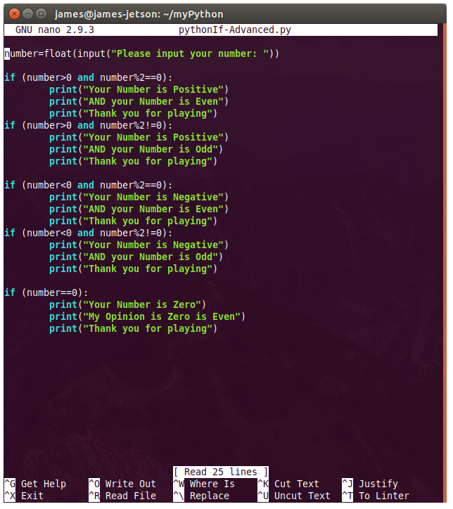
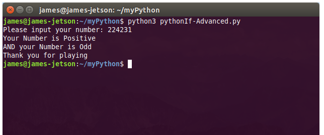
The purpose of this posting is merely to introduce and review Python iterative functions. The IF statement, While, and For to include Arrays are common structural program elements involved in projects around SBC technologies, or in this case the NVIDIA Jetson Nano. In this case, a simple program is set up to indicate the syntax written in the Linux nano utility launched from an Ubuntu terminal window. First the code is written for each iterative program type and there after it is executed to demonstrate expected results.

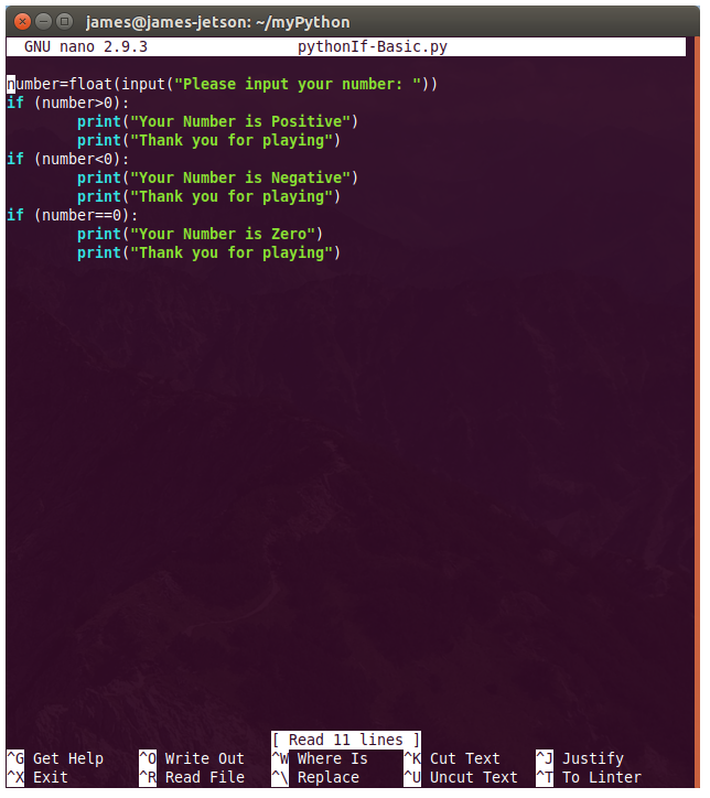
If Statement with conditional operators based upon a user entered number.
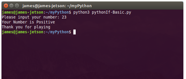
Executed program instructions to operate the program and obtain results.
If Statement with conditional operators based upon a user entered number. A modified version of the basic IF Statement program to indicate Even or Odd condition of a computed result.
Executed program instructions to operate the program and obtain positive or negative results.
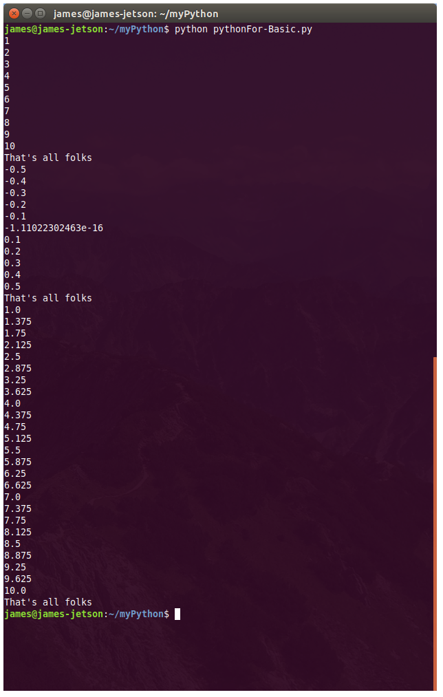
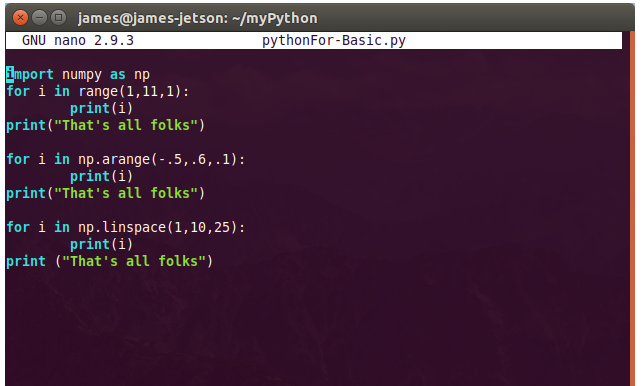
An auto increment method of sequential count between a range of numbers. Using the For Statement to hold condition true and display to screen with appropriate formatting until finished.
All three types of numerical and sequential computation using the For Statement to demonstrate the range, arrange, and linspace functions of Python.
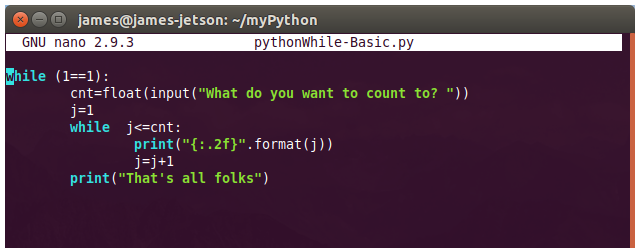
The While Statement that makes use of a float data type input to obtain a maximum count number. Incremented count occurs within the While loop with the displayed number appropriately formatted until the final number is reached.
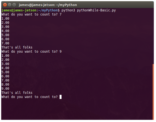
Demonstrated operation of program to indicate results of While Statement. Where operation counts by an increment of 1 and remains in a loop until completion and exit from that loop.
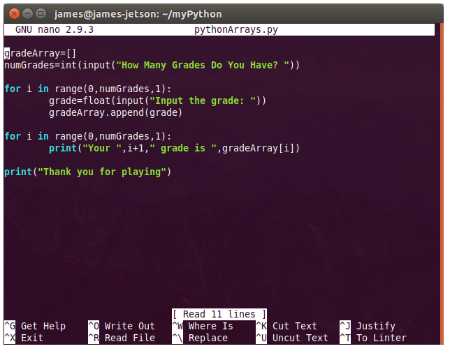
Using a For Statement to demonstrate the function and use of Arrays. Code defines the parameters of two arrays that includes one for grade entries and the other for displayed results.
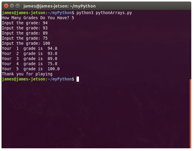
The For loop statement to accept user inputs and thereafter display all results accordingly.