Archive | Engineering RSS feed for this section

DC Motor with Variable Speed Control by Joystick

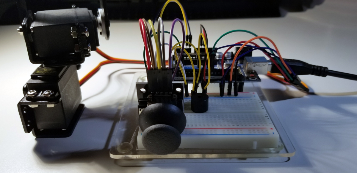
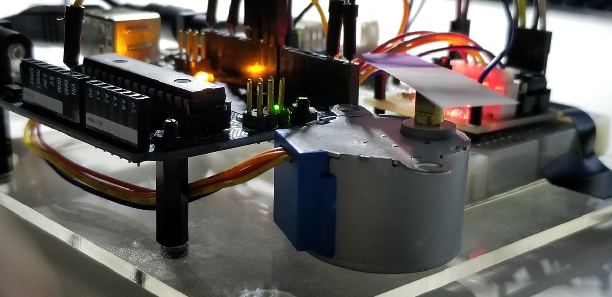
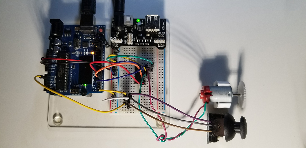
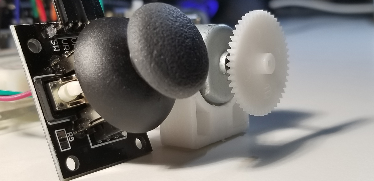
This project makes use of a thumb joystick to control the direction of shaft rotation on a DC motor. The joystick also controls the rotational speed of the motor shaft by how far it is moved horizontally (y-axis). With the joystick on center and at rest, the DC motor doesn’t rotate. However, gradually moving the joystick horizontally to the right increases the speed of the motor until a maximum value permitted by a L293 motor controller. The same method of variable speed control is achieved in reverse with its negative limit to available speed in the opposite rotational direction.

Joystick, DC Motor and motor controller with Arduino Uno R3.

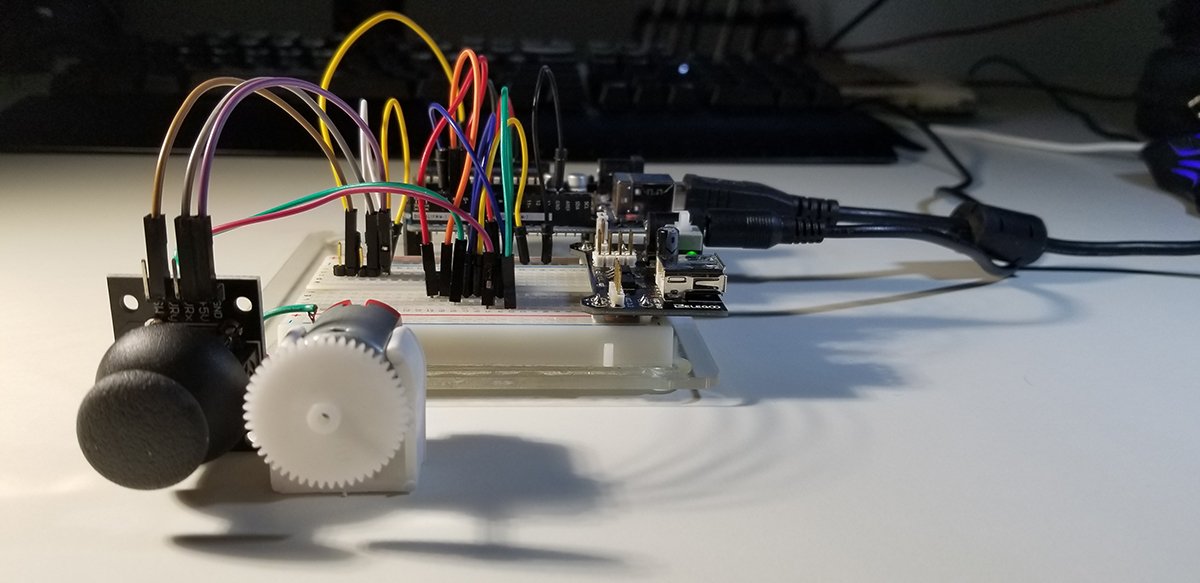
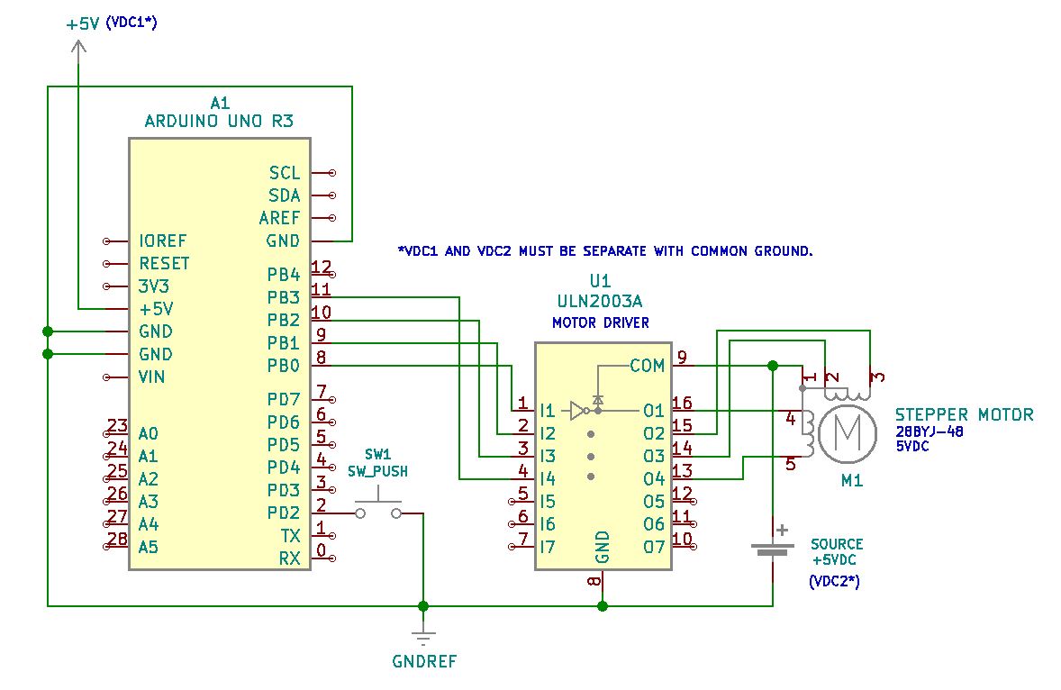
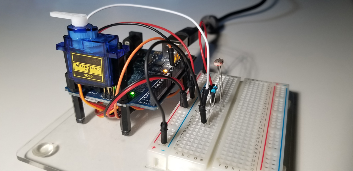
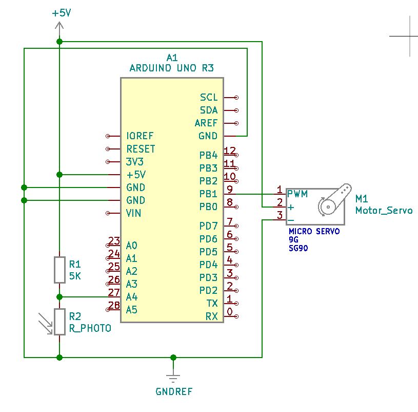
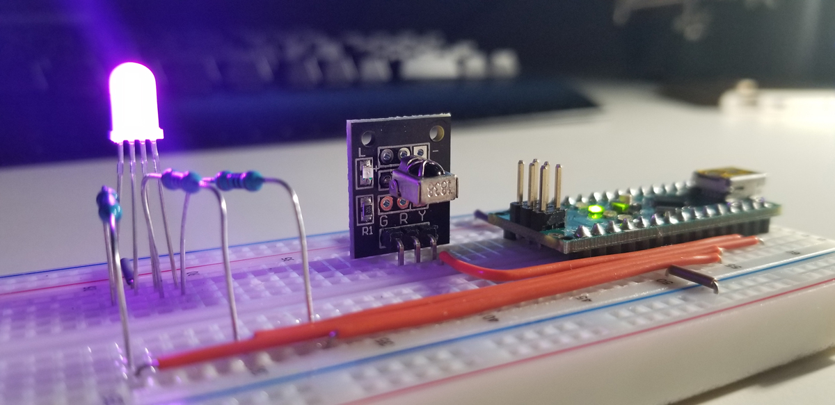
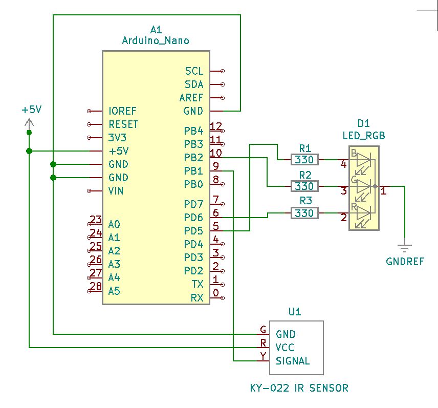
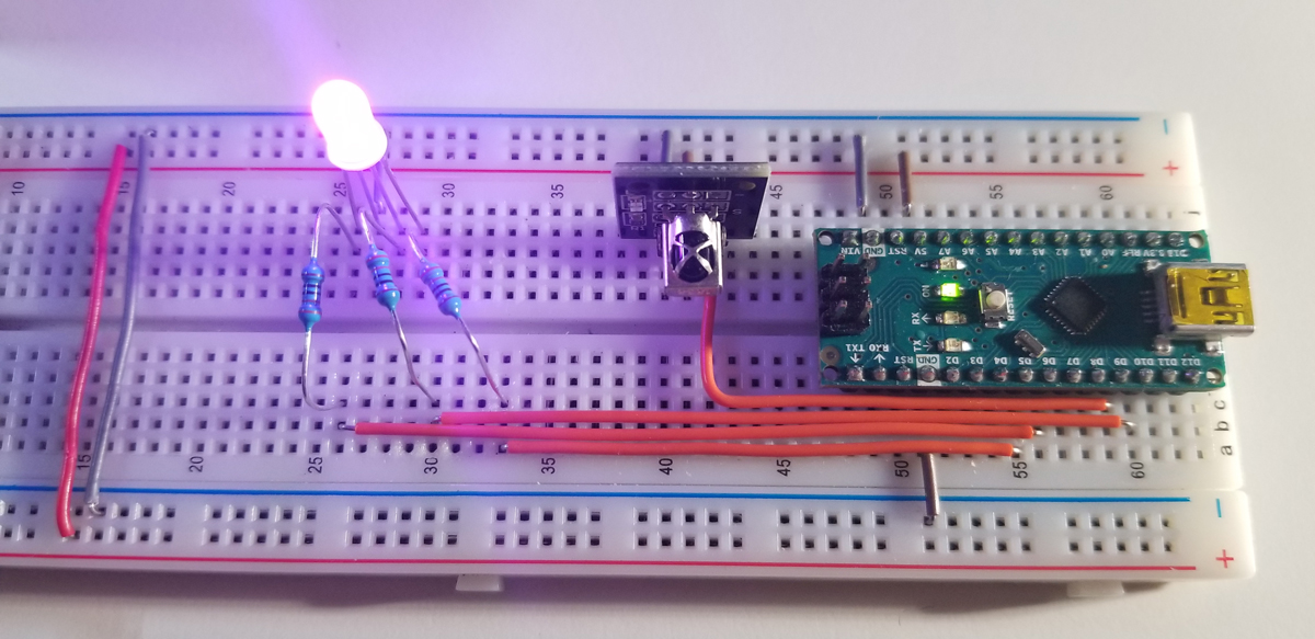
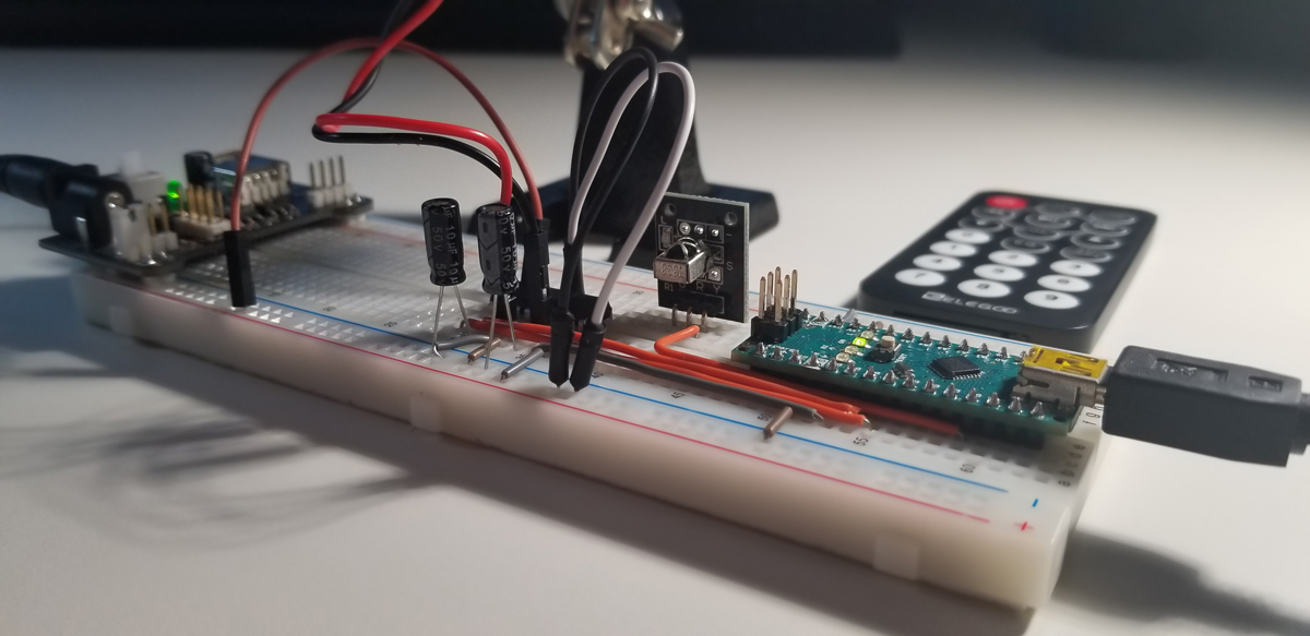
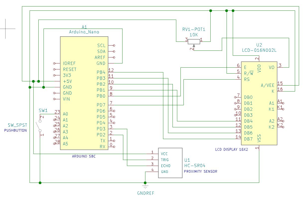
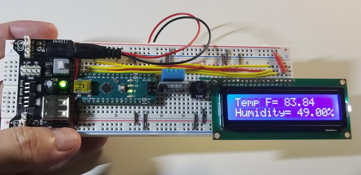
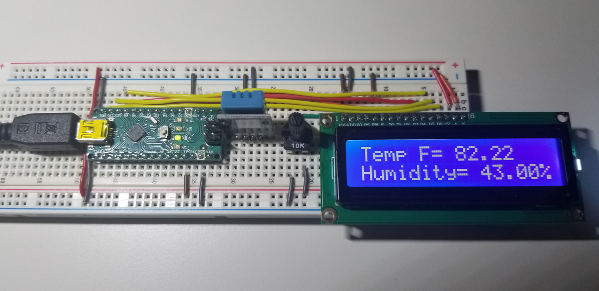
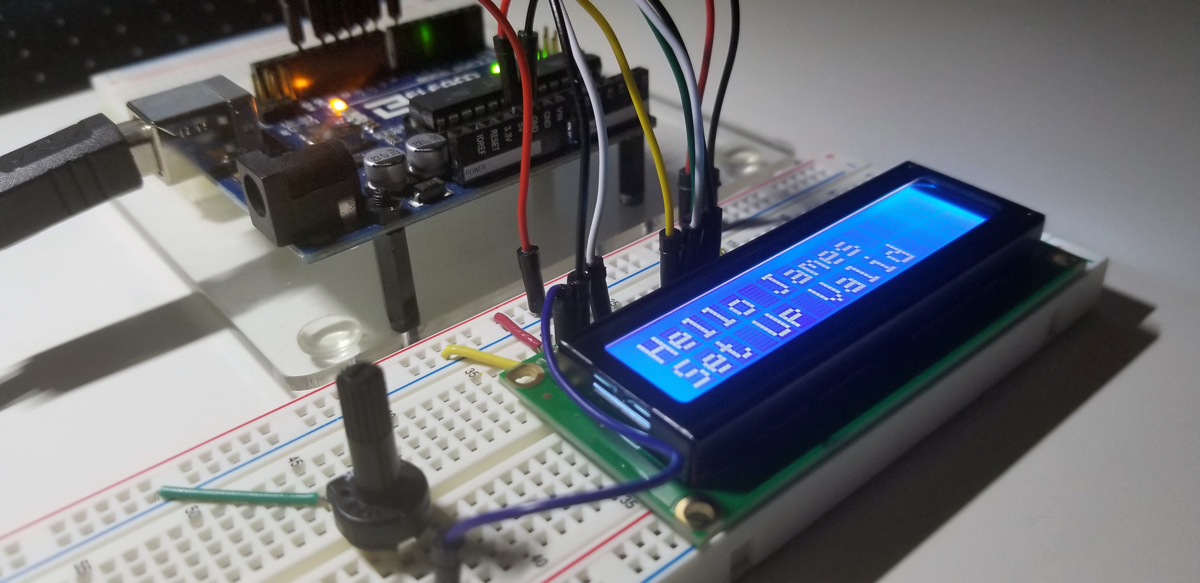
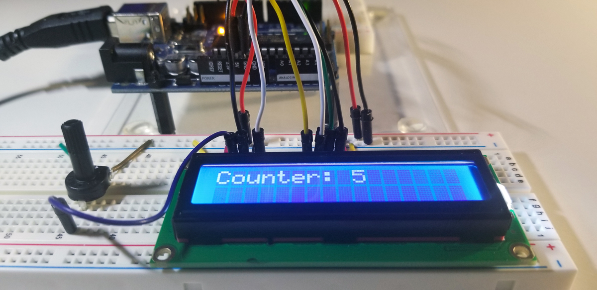
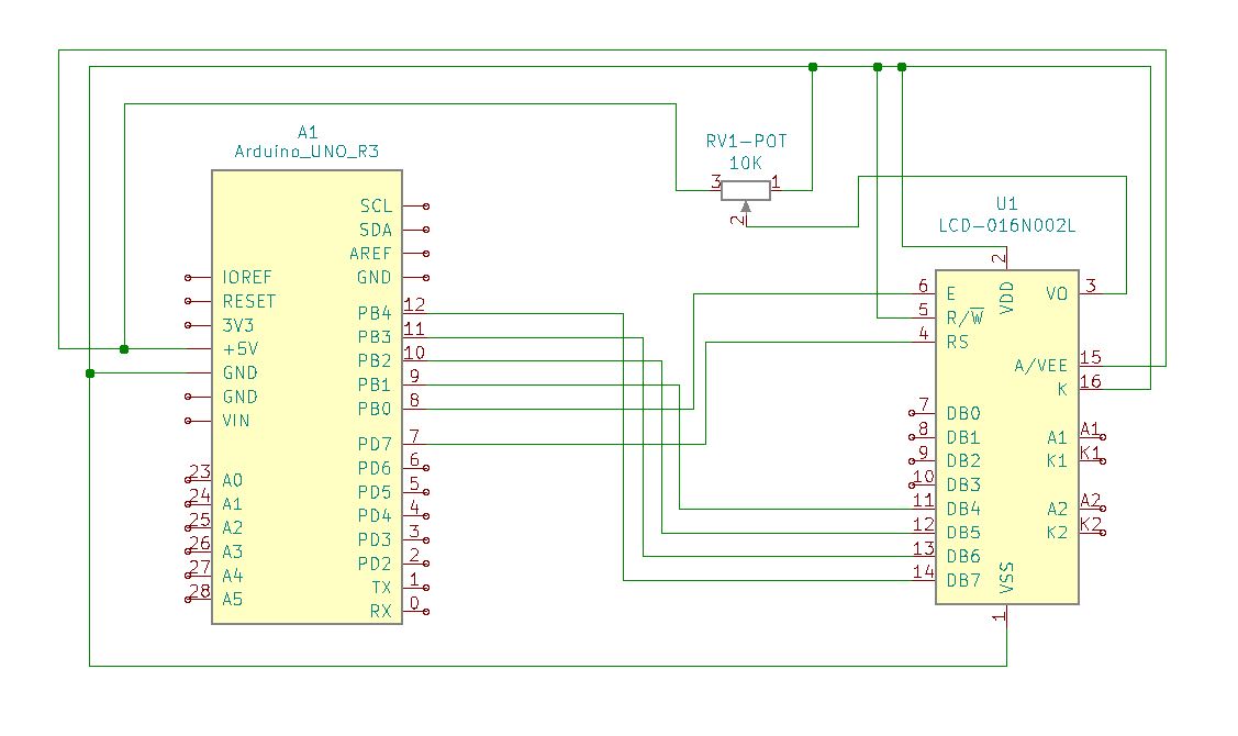
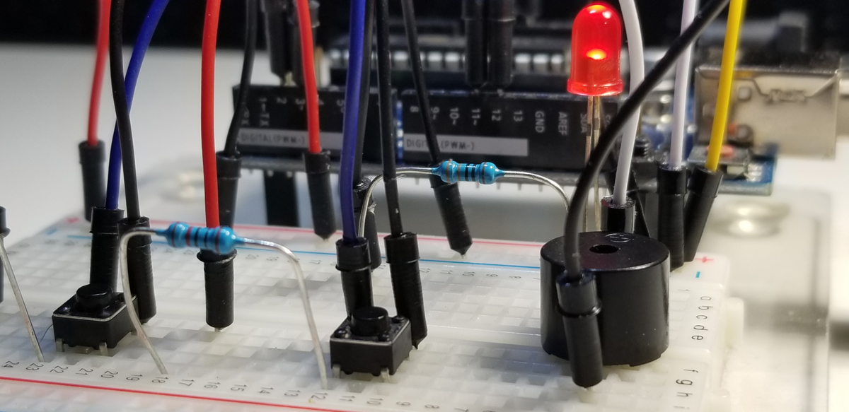
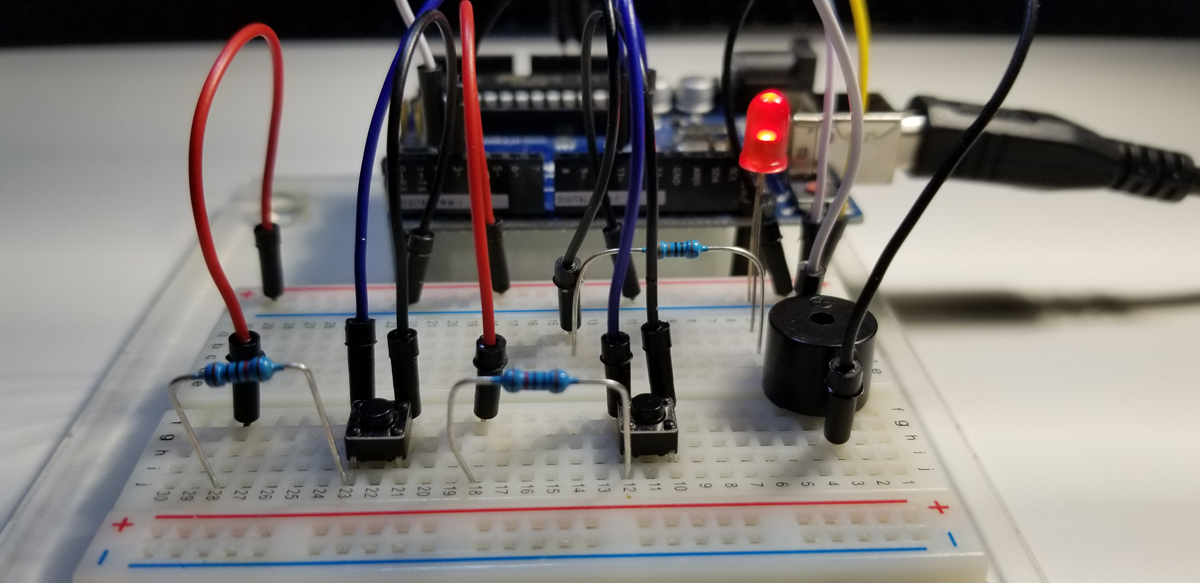
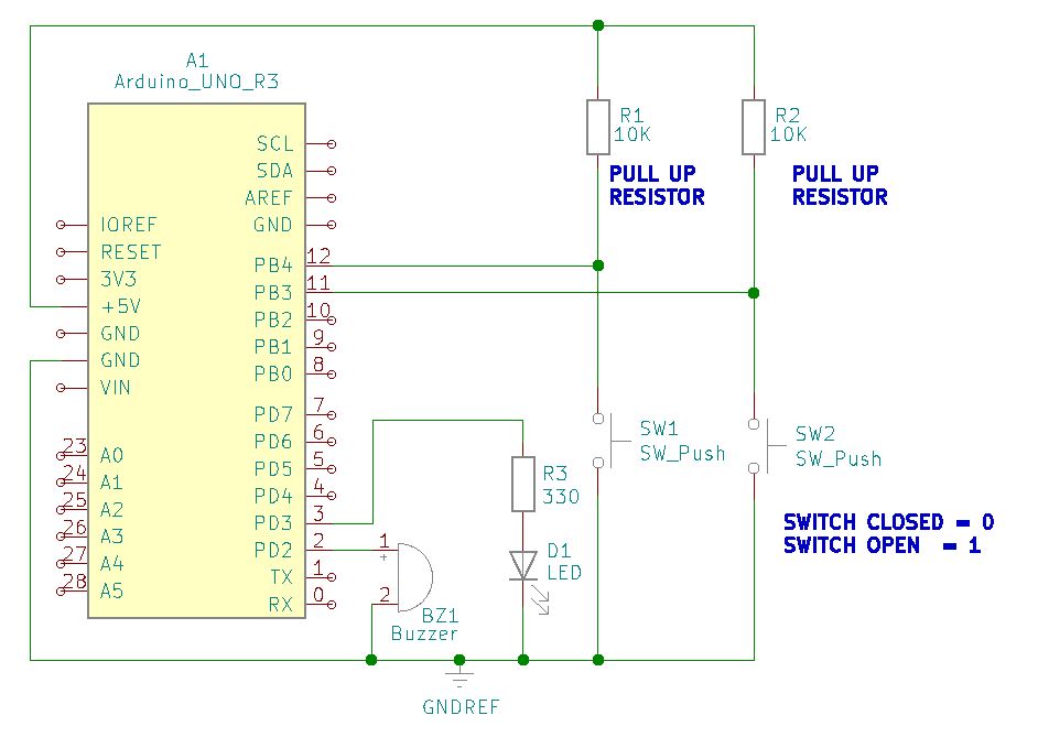
Further details that correspond to this photo are given in the schematic diagram below. The schematic diagram provides specific connection details to indicate where system components are placed and terminated.
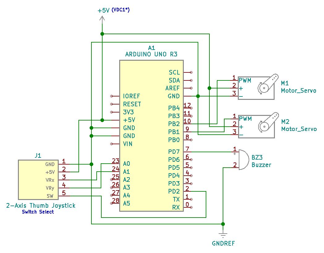
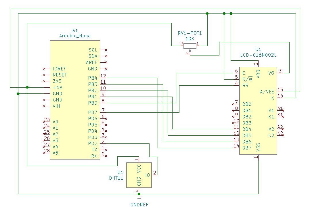
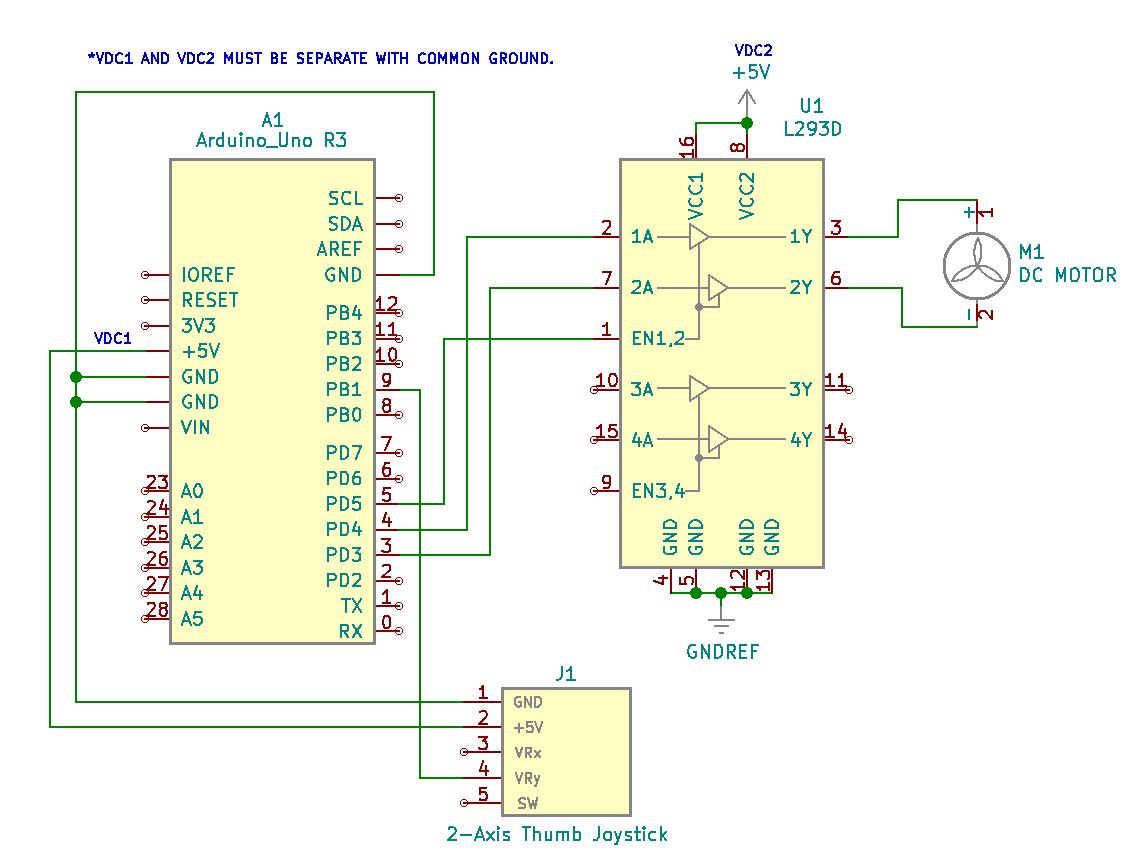
Project hook up details further explained in schematic below.

Project Schematic:

Schematic diagram of project to illustrate how the joystick, DC motor, and motor controller interface with each other and the Arduino Uno R3.

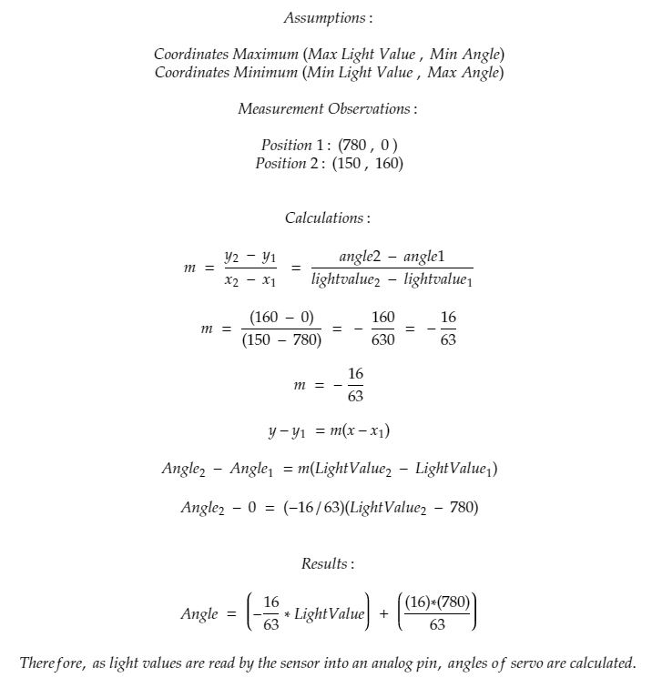
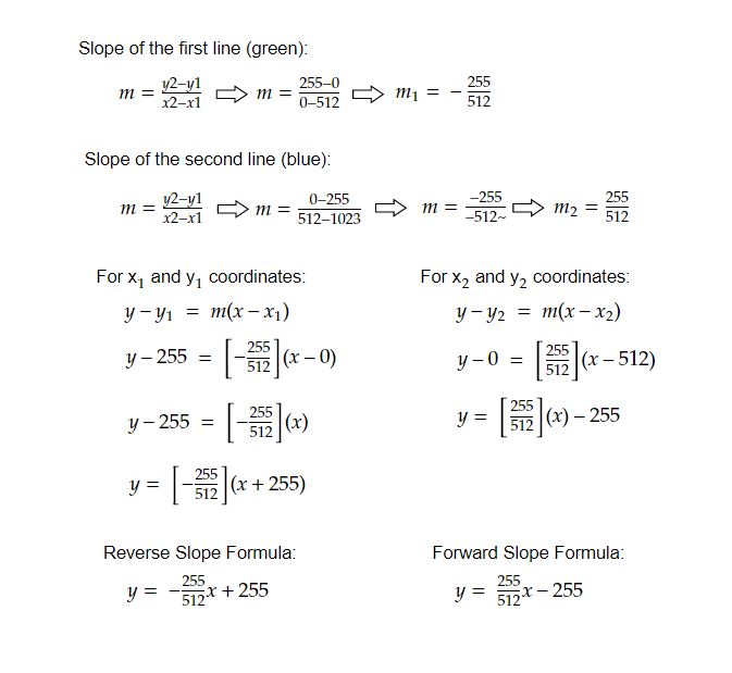
Motor Speed Formulas:

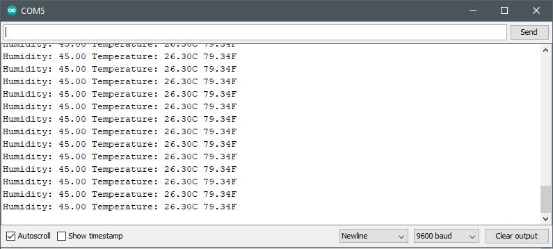
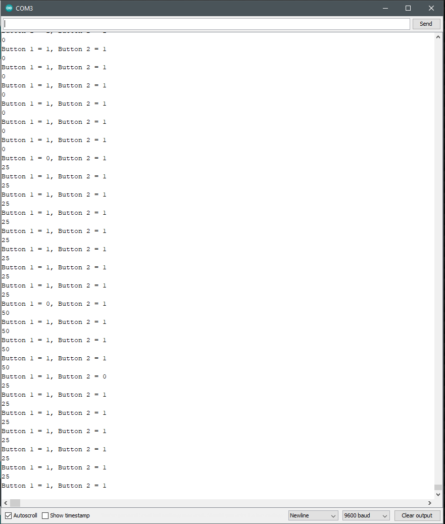
To continuously update the motor speed as a function of gradual joystick movement, it is necessary to read updated joystick values read from memory. As an assigned analog GPIO pin (A1) reads the VRy levels at the joystick, continuous updates are made to memory in order to change motor speed and direction.

Forward and reverse formulas derived for insertion into controller code. To originate continuously changing motor speeds from 0 to 255 or 0 to -255 as read and interpreted analog joystick values between 0 and 1023 (with 512 on center and at rest).

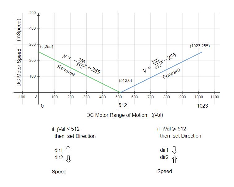
Continuously changing joystick values read into memory becomes calculated for increased or decreased speed adjustment either in a forward or reverse direction. The positive y-axis movement rotates the motor shaft clockwise while the negative y-axis joystick movement rotates the motor shaft counter-clockwise. Both at continuously variable speeds depending upon the joystick’s position off-center from its physically at-rest state.

Thumb joystick and DC Motor suitable for microcontroller use.

Project Review:

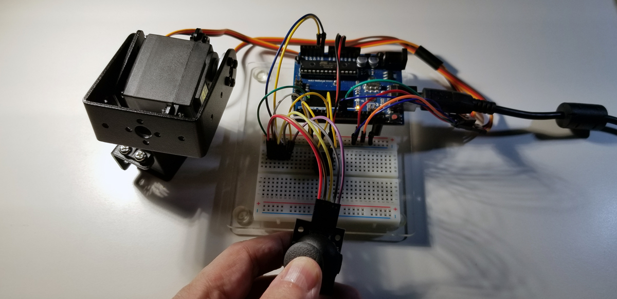
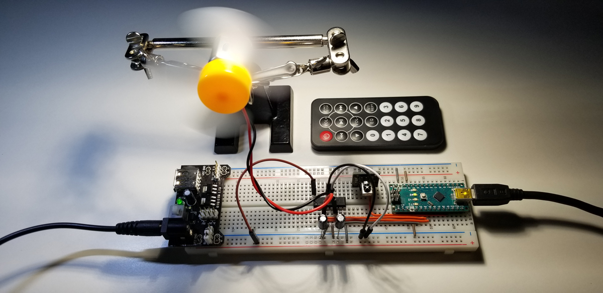
It is necessary to pump the joystick to effect charge momentum for break-through motion and reversal. As demonstrated here, the positive y-axis joystick movement rotates the motor shaft clockwise while horizontally negative joystick movement rotates the shaft counterclockwise. The thumb joystick is inverted in this video, so the opposite lateral motion appears counter-intuitive. Reorient the joystick 180 degrees and its motion directly corresponds to the positive and negative movement for positive and negative rotation.
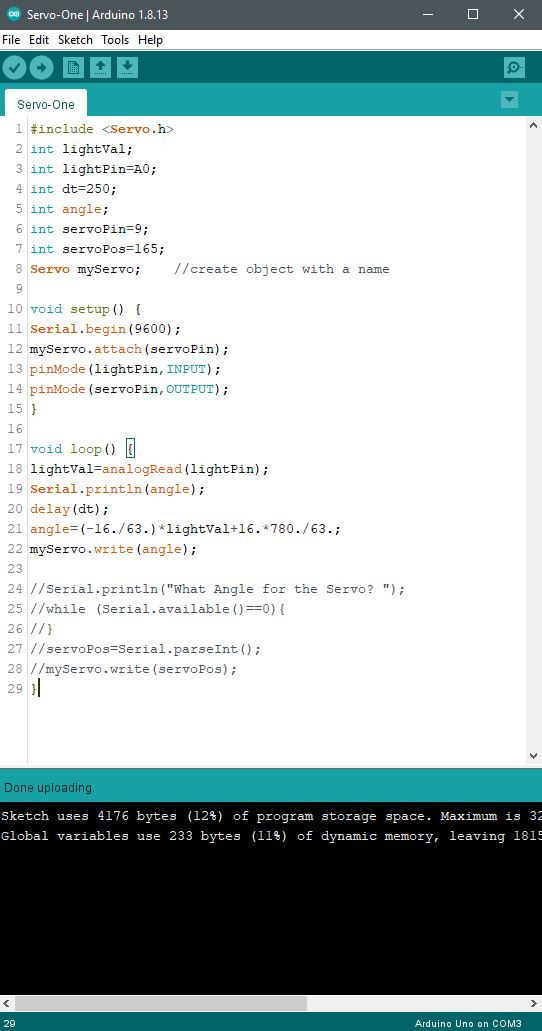
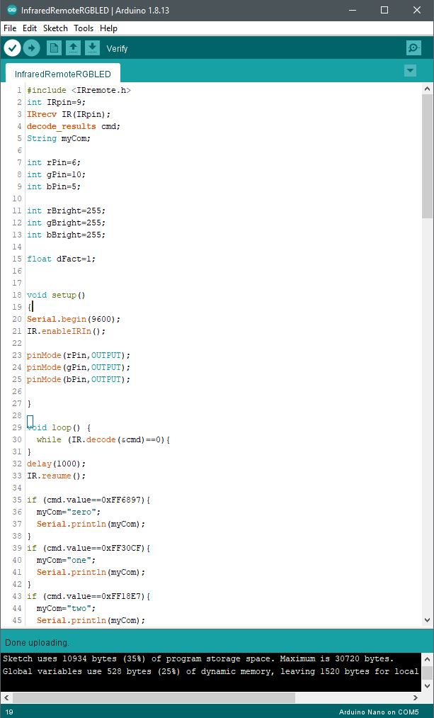
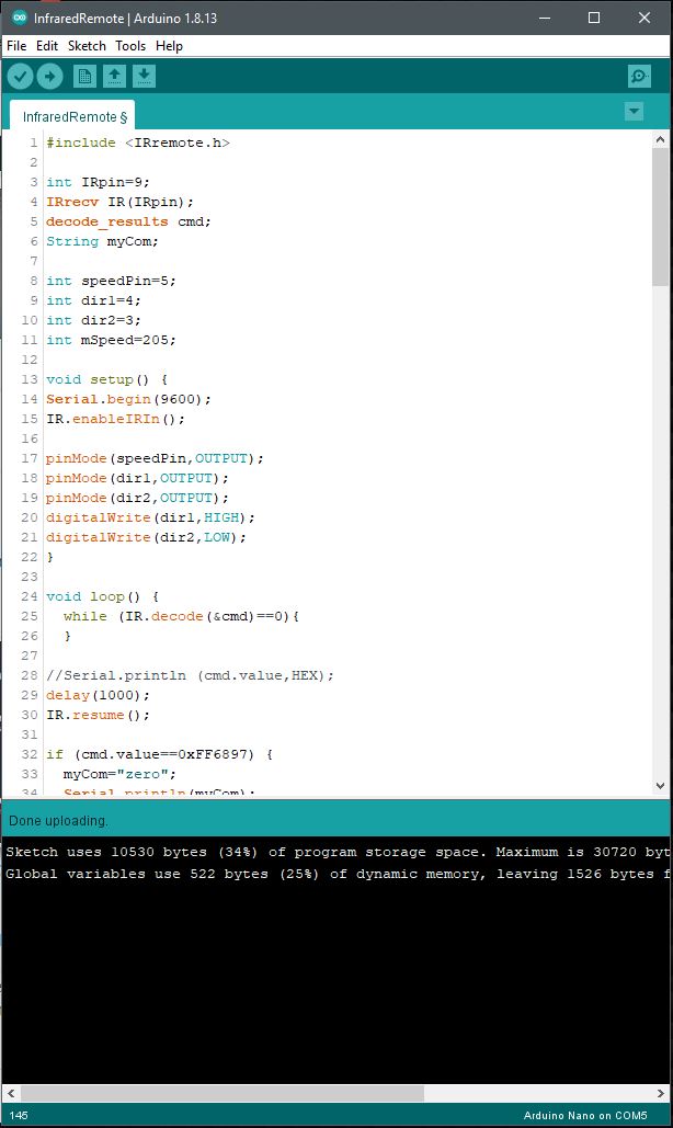
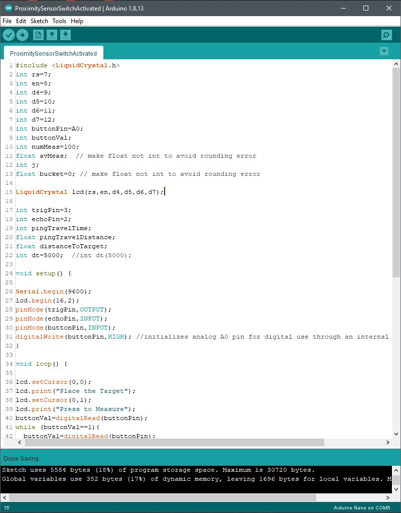
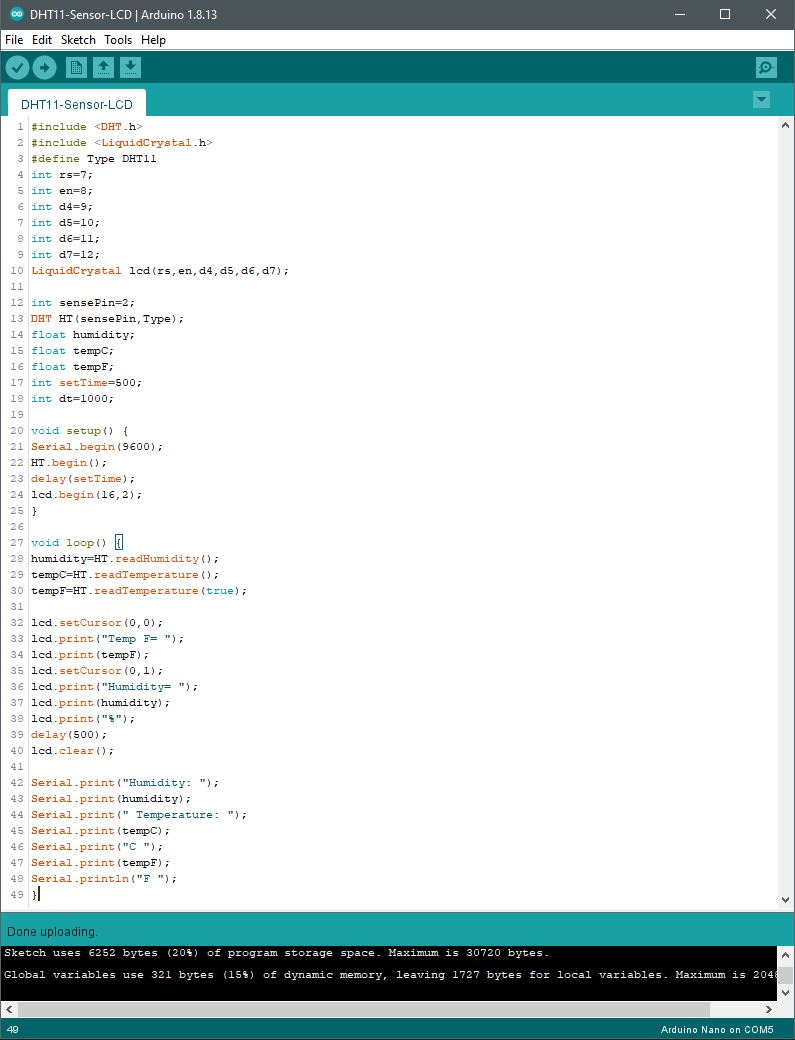
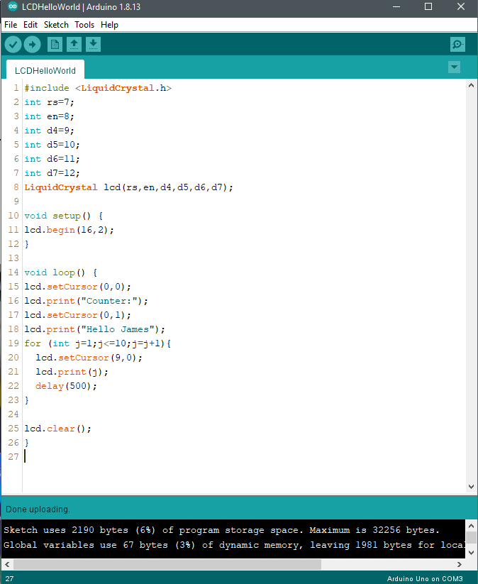
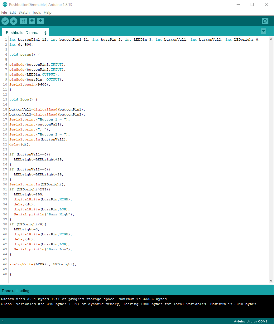

Code Example:

int speedPin=5;
int dir1=4;
int dir2=3;
int mSpeed;
int jPin=A1;
int jVal;

void setup()
{
pinMode(speedPin,OUTPUT);
pinMode(dir1,OUTPUT);
pinMode(dir2,OUTPUT);
pinMode(jPin,INPUT);
Serial.begin(9600);
}

void loop()
{
jVal=analogRead(jPin);
Serial.println(jVal);

if (jVal<505)
{
delay(25);
digitalWrite(dir1,LOW);
digitalWrite(dir2,HIGH);
mSpeed=-255./512.jVal+255.; //derived equation
delay(100);
analogWrite(speedPin,mSpeed);
}

if (jVal>=505)
{
delay(25);
digitalWrite(dir1,HIGH);
digitalWrite(dir2,LOW);
mSpeed=(255./512.)jVal-255.; //derived equation
delay(100);
analogWrite(speedPin,mSpeed);
}
}

Servo Motors with Two-Axis Joystick Control

This project makes use of two servos (Tiankongrc MG995), servo mounting brackets a 2-axis thumb joystick, an active buzzer, and an Arduino Uno R3. To operate the two servos together it is necessary to mount them perpendicular to each other. Where one servo moves along 180 degrees horizontally (x-axis) and the other moves 180 degrees vertically (y-axis). While the joystick VRx, VRy, and SW terminals are read by the Arduino through its GPIO pins, their coordinates are interpreted and sent to each servo for positioning. Either by a single manual motion event or as movement continuously read at the servos to rotate from one position to the next.

Two servos, 2-axis thumb joystick, active buzzer, and an Arduino Uno R3.

The active buzzer sounds when the joystick is depressed. It acts as a toggle to represent a select function that corresponds to typical X,Y positioning at a specific point along its movement.

Rotational Movement Control with the Thumb Joystick.

Project Schematic:

Through pulse width modulation pin connections on the Arduino, simultaneously movement control is achieved at both servos. Along with voltage and ground connections shared with the joystick, separate analog connections are terminated for analogRead instructions at the Arduino controller.

Dual X & Y servos with a 2-axis thumb joystick makes use of both PWM and analog input pins.

Project Review:

This video demonstrates the servo motor’s range of motion and precise positioning as the joystick is controlled with its push-button switch.


Code Example:

#include <Servo.h>
Servo Xservo;
Servo Yservo;

int Xpin=A0;
int Ypin=A1;
int Spin=2;
int XSpin=9;
int YSpin=10;
int buzzPin=7;
int WVx;
int WVy;
int Xval;
int Yval;
int Sval;
int dt=200;

void setup()
{
Serial.begin(9600);
pinMode(Xpin,INPUT);
pinMode(Ypin,INPUT);
pinMode(Spin,INPUT);
pinMode(XSpin,OUTPUT);
pinMode(YSpin,OUTPUT);
pinMode(buzzPin,OUTPUT);

Xservo.attach(XSpin);
Yservo.attach(YSpin);

digitalWrite(Spin,HIGH);
}

void loop() {
Xval=analogRead(Xpin);
WVx=(180./1023.)Xval; Yval=analogRead(Ypin); WVy=(180./1023.)Yval;
Sval=digitalRead(Spin);

Xservo.write(WVx);
Yservo.write(WVy);

if (Sval==0)
{
digitalWrite(buzzPin, HIGH);
}
else
{
digitalWrite(buzzPin, LOW);
}

delay(dt);
Serial.print(“X Value = “);
Serial.print(Xval);
Serial.print(” Y Value = “);
Serial.print(Yval);
Serial.print(” Switch State is “);
Serial.println(Sval);
}


Stepper Motor with Direction Control & Reversal

This project involved a 5VDC stepper motor and its corresponding ULN2003 driver assembly. Stepper motors are unique from servos or DC motors because they are very precise, have a full range of motion, and they can produce a lot of torque. This specific motor permits 2048 steps according to its specifications, so each step represents a high level of rotational movement granularity in a small package. –The purpose of the system is to evaluate a simple stepper motor along with its driver assembly to understand their behavior, limitations, and performance characteristics.

The normally closed micro-switch provides a toggle for the stepper motor shaft to move in either a forward or reverse direction. Directionality is set by a code condition determined by the toggle switch transition states whereas the switch is depressed to activate a change of direction opposite the prior rotational motion. Programmatically, the rotational speed is set to about 10 RPM in this project, but speeds are assigned slower as desired.

ULN2003 Assembly with Motor and Arduino connections.

Stepper motors are found among many applications today. They allow for precision movement and control of hardware throughout various industries, households, or personal devices. They open lids, doors, and windows. They drive gears to rotate lamps, sensors, cameras, and so forth. The use-cases of stepper motors are very wide-spread.

The ULN2003 IC chip located on this assembly is really an array of Darlington pairs that drive up to 500mA at 50VDC. As a current boost is produced from the second Darlington transistor staged after the first of its pair, sufficient current capacity is presented to the terminals of the assembly that hosts the ULN2003. This assembly provides for input and output connections between the stepper motor and an Arduino unit along with LEDs and voltage supply terminals.

Each LED on the ULN2003 indicates the step activity of all four stators. Notice that each stator is in a fixed position with coil wrapping. As each coil is charged on and off, the motor shaft rotates a single step.

The internal workings of the stepper motor convert electrical energy (5VDC in this case) to mechanical movement. In an incremental fashion, all four coils in a fixed position advance the internal rotation in clockwise or counter-clockwise steps (depending upon motor capability). The shaft assembly that extends outside of the motor enclosure provides for a mechanical attachment to get practical use of the stepper motor.

The 28BYJ-48 stepper motor and its ULN2003 driver assembly are separately powered from the Arduino UNO R3 host. Stepper motors draw extra high current to require more power than what an Arduino can support. So this motor runs from a separate wall adapter that delivers 5VDC at 3.5A (~18W).

It is because of this higher motor current requirement that the Darlington pair boost is provided through the ULN2003 assembly. So it is necessary to recognize that motors must be matched with a corresponding driver board that includes a suitable current capacity along with the appropriate types of input and output terminations matched to the motor. Normally, stepper motors have four wires for driver connectivity.

Project Schematic:

The ULN2003 driver hosts a ULN2003 IC chip that terminates to a 28BYJ-48 stepper motor since it is matched to the motor’s operating requirements.

Project Review:

This video demonstrates the stepper motor’s direction of rotation as the pushbutton switch is toggled.


Arduino IDE:

Code Setup:

#include <Stepper.h>
int stepsPerRevolution=2048; //get this step count from the spec sheet
int motSpeed=10; //10 RPM
int dt=500;

int buttonPin=2;
int motDir=1; //variable to keep track direction of motor shaft
int buttonValNew; //present state of the button switch
int buttonValOld=1; //prior state of the button switch initiated as 1 (not pressed)

Stepper myStepper(stepsPerRevolution, 8,10,9,11);
//the numbers are the pin sequence for a specific driver and specific motor connected in a specific way

void setup() {
Serial.begin(9600);
myStepper.setSpeed(motSpeed);
pinMode(buttonPin,INPUT);
digitalWrite(buttonPin,HIGH); //puts a pullup high state onto the button pin
}

void loop() {
buttonValNew=digitalRead(buttonPin);
if (buttonValOld==1 && buttonValNew==0){
motDir=motDir(-1); } //button transition (1,0) sets condition for motor direction change buttonValOld=buttonValNew; myStepper.step(motDir1);

}


Tilt Switch with LED Indicator and Fan Interrupt

This project was about making a tilt sense system that involves a motor or fan. The system is also programmed and set up with a tip sense light. It simulates a tip-over or roll-over situation and when the system reaches a 90-degree angle from level. At 90 degrees, the sensor drive signal shuts everything down through the Nano. It also has industrial applications as there are different tilt switches at different angles.

Tilt detection system that senses motion up to a 90 degree angle before motor or fan cut-off. The green LED indicator represents a normal state. While the red LED illumination represents an abnormal state when the system tilts 90 degrees or more.

Normal state of operation with function fan or motor.

Abnormal state of operation with fan interrupted.

Project Schematic:

The system requires separate power supplies to support a higher current draw motor or fan unless the entire system provides for sufficient power or current draw. Motors and fans normally draw much more current that the controller or sensor devices hosted within its system.

A tilt switch is really just a type of motion sensor that activates after a certain angle from a reference point is reached. Among various approaches toward level detection and sensor motion, this project uses a canister tilt switch that uses a small internal ball that interrupts a closed switch path as it is rolled from one position to another at the component’s specified angle.

At the specified angle, the tilt switch path is open and no further connection between its leads is permitted. For example, in a level state, a tilt device’s upright position settles an internal miniature metal ball for a closed switch path (or “on” function). Conversely, when the position tips beyond its specified angle, the internal metal ball moves to another position where the connection path between the two switch leads become interrupted (or “off” function).

Tilt switch canister with two leads and internal unseen miniature ball.

Project Operation:

The demonstration of this system zooms in on the states of LED illumination and fan movement as its position changes from level (0-degrees) to upright (90-degrees).


Code Setup:

int speedPin=5;
int dir1=4;
int dir2=3;
int mSpeed=255;
int tiltPin=2;
int tiltVal;

int redPin=7;
int greenPin=6;

void setup() {
Serial.begin(9600);
pinMode(speedPin,OUTPUT);
pinMode(dir1,OUTPUT);
pinMode(dir2,OUTPUT);
pinMode(tiltPin,INPUT);
digitalWrite(tiltPin,HIGH); //to assign as pullup pin

pinMode(redPin,OUTPUT);
pinMode(greenPin,OUTPUT);
}

void loop() {
digitalWrite(dir1,LOW);
digitalWrite(dir2,HIGH);
tiltVal=digitalRead(tiltPin);
Serial.println(tiltVal);
if (tiltVal==0){
digitalWrite(greenPin,HIGH);
digitalWrite(redPin,LOW);
analogWrite(speedPin,mSpeed);
}
if (tiltVal==1){
digitalWrite(greenPin,LOW);
digitalWrite(redPin,HIGH);
analogWrite(speedPin,0);
}
}


Light Sensor Control of Servo with Photoresistor

This project makes use of a photoresistor as a light sensor to control the movement of a servo motor’s shaft. The change of position in the servo motor’s output shaft moves from 0 degrees to 180 degrees maximum depending upon the light intensity present at the photoresistor. The highest level of light places the output shaft arm to 0 degrees while the absence of light at the sensor moves the output shaft arm to about 180 degrees. The actual range of motion is limited to the quality of the servo, but 180 degrees is generally the limit.

All components in the system are powered by the Arduino Uno (R3) through the USB connection from a local supply or computer.

The purpose of the project is to demonstrate the simple use of a servo for the automatic positioning of a physical object as a function of light intensity. The light sensor is read at an analog GPIO pin to get continuously variable values to read into memory via an analogRead operation. The motor response to continuous analog read activity (with a small 250ms delay between each) is calculated to a PWM output level written to a port where the output shaft moves at a corresponding angle.

The micro servo mounts nicely onto the Arduino Uno in a secure way through the two standoffs on the controller. The various terminal connections in this photo correspond to the schematic diagram posted below.

The resistor is 5K-ohms with the analogRead connection between it and the photoresistor for active continuous input to the Arduino.

Project Operation:


Project Schematic:

Arduino IDE:

Servo Output Angle Calculations:

Code Setup:

#include <Servo.h>
int lightVal;
int lightPin=A4;
int dt=250;
int angle;
int servoPin=9;
int servoPos=165;
Servo myServo; //create object with a name

void setup() {
Serial.begin(9600);
myServo.attach(servoPin);
pinMode(lightPin,INPUT);
pinMode(servoPin,OUTPUT);
}

void loop() {
lightVal=analogRead(lightPin);
Serial.println(angle);
delay(dt);
angle=(-16./63.)*lightVal+(16.*780.)/63.;
myServo.write(angle);
}


Color and Light Control via Infrared Sensor

This project runs with an IR sensor that reads a remote control’s Hexadecimal data bursts as its buttons are selected. Each button represents a function that becomes executed programmatically within the Nano to affect the color and light intensity at the LED. As hex values are decoded into the Arduino Nano via the IR sensor, a conditional statement evaluates the decoded value held in memory. For each button selected, the conditional statement evaluates the hex value unique to each.

Functional Demonstration Video:

The video demonstrates a visual walkthrough of power on, off, color selection, and increase or decrease of each color brightness. Control is demonstrated through the remote control through the wireless communication made through infrared modulation of binary data decoded or translated into useful hex values for programming and operation.


Project Schematic:

The schematic diagram of the circuit is simple. The connections are defined as illustrated as power, ground, and pin-to-pin terminations are made. The RGB LED supported with three 330-ohm current limiting resistors, but this value can be adjusted higher as desired.

It is necessary to select PWM pins to connect the RGB LED as needed. Since values of 0 to 255 are applied to each red, green, and blue LED pin, varying levels of intensity are adjustable in programmatic increments or decrements. This is only possible through the use of PWM GPIO pins as indicated by the ~ mark on an Arduino unit or pin-out diagram. It is important to note that the <IRremote.h> library file ( version 2.2.3) is not compatible with the use of pins 3 and 11 for PWM operation.

The infrared sensor accepts HEX encoded pulse emissions from the remote control to instruct the Arduino Nano to combine red, green, and blue values to a single LED device. Each Nano pin produces pulse width modulation power to set mixed colors with up and down brightness for each color selected. The color palette possibilities with this project are very high.
The simplicity of the circuit is made possible through the use of the Nano controller, its processor, and GPIO interfaces.

Arduino IDE:

The IR sensor reads a remote control’s Hexadecimal data stream as its buttons are selected. Each button represents a function that becomes executed programmatically. As hex values are decoded into the Arduino Nano via the IR sensor, a conditional statement evaluates the decoded value held in memory. For each button selected, the conditional statement evaluates the hex value unique to each.

Code Setup:

#include <IRremote.h>
int IRpin=9;
IRrecv IR(IRpin);
decode_results cmd;
String myCom;

int rPin=6;
int gPin=10;
int bPin=5;

int rBright=255;
int gBright=255;
int bBright=255;

float dFact=1;

void setup()
{
Serial.begin(9600);
IR.enableIRIn();

pinMode(rPin,OUTPUT);
pinMode(gPin,OUTPUT);
pinMode(bPin,OUTPUT);
}

void loop() {
while (IR.decode(&cmd)==0){
}
delay(1000);
IR.resume();

if (cmd.value==0xFF6897){
myCom=”zero”;
Serial.println(myCom);
}
if (cmd.value==0xFF30CF){
myCom=”one”;
Serial.println(myCom);
}
if (cmd.value==0xFF18E7){
myCom=”two”;
Serial.println(myCom);
}
if (cmd.value==0xFF7A85){
myCom=”three”;
Serial.println(myCom);
}
if (cmd.value==0xFF10EF){
myCom=”four”;
Serial.println(myCom);
}
if (cmd.value==0xFF38C7){
myCom=”five”;
Serial.println(myCom);
}
if (cmd.value==0xFF5AA5){
myCom=”six”;
Serial.println(myCom);
}
if (cmd.value==0xFF42BD){
myCom=”seven”;
Serial.println(myCom);
}
if (cmd.value==0xFF4AB5){
myCom=”eight”;
Serial.println(myCom);
}
if (cmd.value==0xFF52AD){
myCom=”nine”;
Serial.println(myCom);
}
if (cmd.value==0xFFA25D){
myCom=”pwr”;
Serial.println(myCom);
}
if (cmd.value==0xFF629D){
myCom=”v+”;
Serial.println(myCom);
}
if (cmd.value==0xFFE21D){
myCom=”fun”;
Serial.println(myCom);
}
if (cmd.value==0xFF22DD){
myCom=”rew”;
Serial.println(myCom);
}
if (cmd.value==0xFF02FD){
myCom=”play”;
Serial.println(myCom);
}
if (cmd.value==0xFFC23D){
myCom=”ff”;
Serial.println(myCom);
}
if (cmd.value==0xFFE01F){
myCom=”dn”;
Serial.println(myCom);
}
if (cmd.value==0xFFA857){
myCom=”v-“;
Serial.println(myCom);
}
if (cmd.value==0xFF906F){
myCom=”up”;
Serial.println(myCom);
}
if (cmd.value==0xFF9867){
myCom=”eq”;
Serial.println(myCom);
}
if (cmd.value==0xFFB04F
){
myCom=”st”;
Serial.println(myCom);
}
if(myCom==”pwr”){
rBright=255;
gBright=255;
bBright=255;
dFact=1;
}

if(myCom==”fun”){
rBright=0;
gBright=0;
bBright=0;
dFact=0;
}
//white
if(myCom==”zero”){
rBright=255;
gBright=255;
bBright=255;
}
//red
if(myCom==”one”){
rBright=255;
gBright=0;
bBright=0;
}
//green
if(myCom==”two”){
rBright=0;
gBright=255;
bBright=0;
}
//blue
if(myCom==”three”){
rBright=0;
gBright=0;
bBright=255;
}
//cyan
if(myCom==”four”){
rBright=0;
gBright=255;
bBright=255;
}
//magenta
if(myCom==”five”){
rBright=255;
gBright=0;
bBright=150;
}
//yellow
if(myCom==”six”){
rBright=255;
gBright=255;
bBright=0;
}
if (myCom==”dn”){
dFact=dFact0.75; } if (myCom==”up”){ dFact=dFact1.3;
if (dFact>1){
dFact=1;
}
}
analogWrite(rPin,rBrightdFact); analogWrite(gPin,gBrightdFact);
analogWrite(bPin,bBright*dFact);
}


DC Motor Control via Infrared Sensor & Remote

This project accomplishes a few objectives. First, the use of a KY-022 Infrared sensor is incorporated for general familiarity. Second, the IR remote control emits HEX codes for each button pressed, so it is necessary to capture those HEX codes to map them to specific button IDs and functions later developed. Third, to integrate the motor control driver (L293D) with the Arduino Nano to control motor activity such as speed and direction.

The project is supplied by two separate power supplies. The Arduino Nano and IR sensor is powered by the USB connection while the motor driver is powered by the regulated +5VDC supply. The DC motor operates in both forward and reverse motion depending upon a positive or negative voltage presented by the driver. The higher the positive or negative voltage, the higher the speed. The lower the voltage presented from the driver, the lower the speed. The propeller mounted to the DC motor shaft is simply for ease of visibility.

The L293D motor driver interfaces with the Arduino Nano at a few pins. Specifically, forward and backward motor shaft direction (pin 2 & 7) and speed (pin 1). Code control of these GPIO pins is set up through digitalWrite operation for high/low binary direction assignment while the speed of the motor is set by an analogWrite instruction (from 0 to 255). The IR remote control provides for power on / off, forward or reverse direction, increase speed, and decrease speed. The capacitors bypassed at the motor connections are to filter noise that may appear from unwanted radiation conducted back into the system. These capacitors help to snub back EMF otherwise present throughout the circuit.


The Arduino Nano is programmed through the same USB port that powers it. The USB power and data connection to a local computer is not illustrated in this schematic as it is assumed. After programming the USB is detachable provided the Nano is powered by an alternate source such as a power bank, battery, or wall adapter. The connections throughout this system are illustrated for pin-to-pin connectivity between the motor driver, the Arduino Nano, the IR Sensor, and the DC motor.

Arduino Setup:

See the full code in text format below for copy and paste use.
Serial Monitor: During set up, it was necessary to set up a temporary remote control read operation through the IR sensor to get all of the HEX addresses emitted for each keypress. All button names were pressed to get their corresponding HEX values whereby the mapping is complete to assign button unique functions through conditional statements within the program.
Serial Monitor: To track actual IR sensor readings that correspond to motor activity, the Serial Monitor reports back what remote control button press activity occurs. In this example view, the down button is pressed repeatedly to slow motor speed, and the up button is pressed repeatedly to increase motor speed. The power on (pwr) and power off (func) events record the on/off activity of the motor through the IR remote control and its corresponding sensor.

Code Setup:


#include <IRremote.h>

int IRpin=9;
IRrecv IR(IRpin);
decode_results cmd;
String myCom;

int speedPin=5;
int dir1=4;
int dir2=3;
int mSpeed=205;

void setup() {
Serial.begin(9600);
IR.enableIRIn();

pinMode(speedPin,OUTPUT);
pinMode(dir1,OUTPUT);
pinMode(dir2,OUTPUT);
digitalWrite(dir1,HIGH);
digitalWrite(dir2,LOW);
}

void loop() {
while (IR.decode(&cmd)==0){
}

//Serial.println (cmd.value,HEX);
delay(1000);
IR.resume();

if (cmd.value==0xFF6897) {
myCom=”zero”;
Serial.println(myCom);
}
if (cmd.value==0xFF30CF) {
myCom=”one”;
Serial.println(myCom);
}
if (cmd.value==0xFF18E7) {
myCom=”two”;
Serial.println(myCom);
}
if (cmd.value==0xFF7A85) {
myCom=”three”;
Serial.println(myCom);
}
if (cmd.value==0xFF10EF) {
myCom=”four”;
Serial.println(myCom);
}
if (cmd.value==0xFF38C7) {
myCom=”five”;
Serial.println(myCom);
}
if (cmd.value==0xFF5AA5) {
myCom=”six”;
Serial.println(myCom);
}
if (cmd.value==0xFF42BD) {
myCom=”seven”;
Serial.println(myCom);
}
if (cmd.value==0xFF4AB5) {
myCom=”eight”;
Serial.println(myCom);
}
if (cmd.value==0xFF52AD) {
myCom=”nine”;
Serial.println(myCom);
}
if (cmd.value==0xFFA25D) {
myCom=”pwr”;
Serial.println(myCom);
}
if (cmd.value==0xFF629D) {
myCom=”v+”;
Serial.println(myCom);
}
if (cmd.value==0xFFA857) {
myCom=”v-“;
Serial.println(myCom);
}
if (cmd.value==0xFFE21D) {
myCom=”func”;
Serial.println(myCom);
}
if (cmd.value==0xFF22DD) {
myCom=”rwd”;
Serial.println(myCom);
}
if (cmd.value==0xFF02FD) {
myCom=”play”;
Serial.println(myCom);
}
if (cmd.value==0xFFC23D) {
myCom=”ff”;
Serial.println(myCom);
}
if (cmd.value==0xFFE01F) {
myCom=”down”;
Serial.println(myCom);
}
if (cmd.value==0xFF906F) {
myCom=”up”;
Serial.println(myCom);
}
if (cmd.value==0xFF9867) {
myCom=”eq”;
Serial.println(myCom);
}
if (cmd.value==0xFFB04F) {
myCom=”st”;
Serial.println(myCom);
}
if (myCom==”pwr”){
digitalWrite(dir1,LOW);
digitalWrite(dir2,HIGH);
analogWrite(speedPin,205);
}
if (myCom==”func”){
digitalWrite(dir1,LOW);
digitalWrite(dir2,LOW);
analogWrite(speedPin,0);
}
if (myCom==”ff”){
digitalWrite(dir1,LOW);
digitalWrite(dir2,HIGH);
analogWrite(speedPin,mSpeed);
}
if (myCom==”rwd”){
digitalWrite(dir1,HIGH);
digitalWrite(dir2,LOW);
analogWrite(speedPin,mSpeed);
}
if (myCom==”up”){
mSpeed=mSpeed+5;
if (mSpeed>255){
mSpeed=255;
}
analogWrite(speedPin,mSpeed);
}
if (myCom==”down”){
mSpeed=mSpeed-5;
if (mSpeed<0){
mSpeed=0;
}
analogWrite(speedPin,mSpeed);
}
delay(500);
}


Proximity Detection with Distance Sensor HC-SR04

This project involves the use of an HC-SR04 proximity sensor commonly used among robotic devices for purposes of collision avoidance. In this project, the sensor is applied to an Arduino Nano system measure distance from an object and report back the results to a serial monitor on a computer, and an LCD display. This unit is powered via a battery or USB power back for portability.

Distance measurements between object and proximity sensor.

Each measurement is taken once the sensor appears before an object, or if a target object is placed in front of the sensor. Once the target is placed, a user is prompted to press the circuit switch to activate the measurement activity that occurs. The measurement reported to a computer and LCD display is an average of 100 readings between the sensor and the placed object. The Nano programmatically operates a high-speed loop by which each reading event (0 to 100) is cumulatively stored into a memory bucket. Once all reading measurements are taken, the average measurement is obtained by calculating the total by dividing the number of measurements completed into the total bucket value. This function is repeated for each switch/button-press event to activate a measurement.

The integration of all system components is easily made by to combing key elements onto a single perf/vector board, or PCB.

Functional Demonstration Video:


Project Schematic:

The HC-SR04 proximity sensor symbol is available for download from SnapEDA.

Arduino Setup:

Sketch IDE with code entries. The LCD object library and variable declarations are made to set up the conditions necessary to operate the system. As the proximity sensor is set up for each pin (trigger and echo), they function in bidirectional manner. The trigger function is an output from the Nano that sends out an ultrasonic ping to a target object through the transducers on the sensor. As that ping signal reflects back, the transducer picks up the difference in time to translate that into distance. Since the speed of sound is a known constant, and the travel time of the ping signal is measured, the distance measurement is derived. The derived results are sent back to the Nano from the sensor’s echo pin.

Serial Monitor results with object distance change three-times with two measurements in each position. Each measure corresponds the to LCD display reading.

Code Example:

#include <LiquidCrystal.h>
int rs=7;
int en=8;
int d4=9;
int d5=10;
int d6=11;
int d7=12;
int buttonPin=A0;
int buttonVal;
int numMeas=100;
float avMeas; // make float not int to avoid rounding error
int j;
float bucket=0; // make float not int to avoid rounding error

LiquidCrystal lcd(rs,en,d4,d5,d6,d7);

int trigPin=3;
int echoPin=2;
int pingTravelTime;
float pingTravelDistance;
float distanceToTarget;
int dt=5000; //int dt(5000);

void setup() {
Serial.begin(9600);
lcd.begin(16,2);
pinMode(trigPin,OUTPUT);
pinMode(echoPin,INPUT);
pinMode(buttonPin,INPUT);
digitalWrite(buttonPin,HIGH); //initializes analog A0 pin for digital use through an internal pull up resistor.
}

void loop() {
lcd.setCursor(0,0);
lcd.print(“Place the Target”);
lcd.setCursor(0,1);
lcd.print(“Press to Measure”);
buttonVal=digitalRead(buttonPin);
while (buttonVal==1){
buttonVal=digitalRead(buttonPin);
}
lcd.setCursor(0,0);
lcd.clear();
lcd.print(“Measuring…”);
for (j=1;j<=numMeas;j=j+1){
digitalWrite(trigPin,LOW);
delayMicroseconds(10);
digitalWrite(trigPin,HIGH);
delayMicroseconds(10);
digitalWrite(trigPin,LOW);
pingTravelTime=pulseIn(echoPin,HIGH);
delay(25);
pingTravelDistance=(pingTravelTime*765.*5280.*12)/(3600.*1000000);
distanceToTarget=pingTravelDistance/2;
bucket=bucket+distanceToTarget;
}
avMeas=bucket/numMeas;

Serial.print(“Target Distance: “);
Serial.print(distanceToTarget);
Serial.println(” inches”);
lcd.clear();
lcd.setCursor(0,0);
lcd.print(“Target Distance:”);
lcd.setCursor(0,1);
lcd.print(distanceToTarget);
lcd.print(” Inches”);
delay(dt);
}


Portable Temperature & Humidity Monitor System

The purpose of this build is to become more familiar with how to develop a free-standing Arduino system using the Arduino Nano. The Nano is a smaller equivalent to the Arduino Uno, but with fewer interface options. It obviously occupies less space since it is a smaller footprint while having reduced overall dimensions. The project makes use of a DHT temperature and humidity sensor that interfaces with the Nano and it includes a 16×2 LCD display to indicate measurement results.

As temperature and humidity variations appear within the immediate environment, there are readings at the sensor read into the Arduino Nano. The system is configured and programmed to accept those readings and report them to the liquid crystal display. The ambient conditions surrounding the sensor are processed within the Nano to translate sensor data into usable information at the display.
The system is powered by a 9V battery stepped down to a regulated 5VDC supply. The power module supports the Nano, DHT sensor, and LCD display. The power supply module’s detachability renders the Nano accessible for ease programming and alternative power through the Nano’s USB receptacle. This setup removes any permanent tethering with extended life through a power supply module’s USB-A receptacle if a power bank is used instead. The 10K-ohm potentiometer is a brightness control for the LCD display.

The system schematic makes no use of passive components except for the single variable resistor (10K-ohm potentiometer). The direct connections between the Nano and display provide for desired simplicity during build and diagnostics. The DHT11 sensor pin-out provides for clarity about necessary connections at the Nano.

1602A LCD Display Pinout

PinSymbolFunction
1VSSGround
2VDD+5VDC
3V0Contrast
4RSRegister
5R/WRead/Write
6EEnable
7D0Data
8D1Data
9D2Data
10D3Data
11D4Data
12D5Data
13D6Data
14D7Data
15AAnode (+5VDC)
16KCathode (Ground)

Arduino Setup:

To program, edit, or update the firmware within the Arduino Nano, it is necessary to attach a USB connection from computer. The serial connection is made to update settings, configure the Arduino IDE (Sketch)
The conventional structured programming setup applies to this project as with any other. The top of the program specifies libraries to support physical objects or devices in the project such as the DHT sensor and the LCD display in this case. Above the void set up procedure block, relevant variables are declared by data type (integer, float, etc). The void setup initiates devices, Arduino functions, or GPIO pins. The loop functions are the procedure itself that iterates to execute the main process by which the program operates.
To set up and program the Nano, it is necessary to select it under the Board option from the Tool menu. The Port option within the Tools menu may require selection or setup as COM1 – COM5 (or some COM#) to establish a connection to a computer for programming and to run the Serial Monitor under this same Tools menu selection.
To install relevant external device libraries (such as a temperature sensor, or display), it might be necessary to add the device to the Arduino Sketch folder on its host computer (usually C:\Users\[name]\Documents\Arduino\libraries).
An example to install or update a device library from the Manage Libraries selection of the Tools Menu option, provides a dialog box to search by library name or description. In this example, “DHT” is keyed in to find the temp & humidity sensor for installation.
Once the Arduino Sketch IDE is set up and configured with the correct board, serial COM connection, and relevant libraries, the code becomes operable and the serial monitor confirms proper use and setup (if/as applicable).

Code Setup:

#include <DHT.h>
#include <LiquidCrystal.h>
int rs=7;
int en=8;
int d4=9;
int d5=10;
int d6=11;
int d7=12;
LiquidCrystal lcd(rs,en,d4,d5,d6,d7);

int sensePin=2;
DHT HT(sensePin,Type);
float humidity;
float tempC;
float tempF;
int setTime=500;
int dt=1000;

void setup() {
Serial.begin(9600);
HT.begin();
delay(setTime);
lcd.begin(16,2);
}

void loop() {
humidity=HT.readHumidity();
tempC=HT.readTemperature();
tempF=HT.readTemperature(true);

lcd.setCursor(0,0);
lcd.print(“Temp F= “);
lcd.print(tempF);
lcd.setCursor(0,1);
lcd.print(“Humidity= “);
lcd.print(humidity);
lcd.print(“%”);
delay(500);
lcd.clear();

Serial.print(“Humidity: “);
Serial.print(humidity);
Serial.print(” Temperature: “);
Serial.print(tempC);
Serial.print(“C “);
Serial.print(tempF);
Serial.println(“F “);
}


Liquid Crystal Display Setup, Control & Calculator

A common Arduino system typically includes a display of some type. This project was to set up a 16×2 LCD display to an Arduino unit and run it with simple messages that render it available for inputs or computational processing. It produces an informational output of its own, or to correspond to another event controlled by a wider system.

While the LCD display takes up several digital GPIO pins, there are several more remaining to build additional system functions. As either inputs or outputs, the display can read sensor data and trigger a relay, an alarm, or other device as specified. The potentiometer in the project as illustrated in the schematic below controls the LCD character block brightness.
Aside from any additional inputs, controls, or outputs, the LCD can display processes that run within the Arduino unit. Even as depicted here such as a counter or a calculator.

The physical connections between the Arduino and LCD display are through direct jumper connections between GPIO pins to data, control, power, and ground. The potentiometer is simply for character illumination intensity.

The digital GPIO pins that interface to the LCD connect to its data pins. R/W is strapped low to ground.

Arduino 16×2 LCD System Schematic

1602A LCD Display Pinout

PinSymbolFunction
1VSSGround
2VDD+5VDC
3V0Contrast
4RSRegister
5R/WRead/Write
6EEnable
7D0Data
8D1Data
9D2Data
10D3Data
11D4Data
12D5Data
13D6Data
14D7Data
15AAnode (+5VDC)
16KCathode (Ground)

Program & Functional Operation:


Code Setup:

#include <LiquidCrystal.h>
int rs=7;
int en=8;
int d4=9;
int d5=10;
int d6=11;
int d7=12;
LiquidCrystal lcd(rs,en,d4,d5,d6,d7);

void setup() {
lcd.begin(16,2);
}

void loop() {
lcd.setCursor(0,0);
lcd.print(“Counter:”);
lcd.setCursor(0,1);
lcd.print(“Hello James”);
for (int j=1;j<=10;j=j+1){
lcd.setCursor(9,0);
lcd.print(j);
delay(500);
}
lcd.clear();
}

Arduino Setup:

Calculator Setup:

#include <LiquidCrystal.h>
int rs=7;
int en=8;
int d4=9;
int d5=10;
int d6=11;
int d7=12;

float firstNum;
float secNum;
float answer;

String op;

LiquidCrystal lcd(rs,en,d4,d5,d6,d7);

void setup() {
lcd.begin(16,2);
Serial.begin(9600);
}

void loop() {

lcd.setCursor(0,0);
lcd.print(“Input 1st Number”);
while (Serial.available()==0){
}
firstNum=Serial.parseFloat();
lcd.clear();
lcd.setCursor(0,0);
lcd.print(“Input 2nd Number”);
while (Serial.available()==0){
}
secNum=Serial.parseFloat();

lcd.clear();
lcd.setCursor(0,0);
lcd.print(“Operator(+,-,*,/)”);
while (Serial.available()==0){
}
op=Serial.readString();

if (op==”+”){
answer=firstNum+secNum;
}
if (op==”-“){
answer=firstNum-secNum;
}
if (op==””){
answer=firstNumsecNum;
}
if (op==”/”){
answer=firstNum/secNum;
}
lcd.clear();
lcd.setCursor(0,0);
lcd.print(firstNum);
lcd.print(op);
lcd.print(secNum);
lcd.print(” = “);
lcd.print(answer);
lcd.setCursor(0,1);
lcd.print(“Thank You”);
delay(10000);
lcd.clear();
}


Pushbutton Switch Dimmer Control & Alarm

This project controls an increasing and decreasing voltage level in increments to represent a dimmer present at an LED. An in-circuit buzzer serves as an alarm to indicate either a maximum or minimum level is attained. Two separate pushbutton switches are up / down controls at programmable increments.

Both switches are set up in a common physical configuration only attached to separate GPIO ports. The difference between their operation rests within the code. Brightness increments are defined within the code as is the decrements. Each increment and decrement interval is code-defined as both switches are attached as inputs to separate GPIO ports. The LED is simply an indicator of a GPIO output to show what the increments and decrements are doing (increasing and decreasing voltage levels).
The buzzer that operates as an alarm triggers when the pushbutton switch is pressed too much or too long. As increments increase to a cap (255) or decrease to a floor (0), the alarm will sound to indicate there is no further increase or decrease available. The dimming or brightness levels off and goes no further.

One pull up resistor for each pushbutton switch is necessary to correctly assert each GPIO input to control circuit and code activity. Four total GPIO pins used, each one for its dedicated function. There is no attempt to make dual use of a GPIO port.

Project schematic to illustrate connections and devices interfaced to the Arduino SBC.

Program & Functional Operation:


Code Setup:

int buttonPin1=12;
int buttonPin2=11;
int buzzPin=2;
int LEDPin=3;
int buttonVal1;
int buttonVal2;
int LEDbright=0;
int dt=500;

void setup() {
pinMode(buttonPin1,INPUT);
pinMode(buttonPin2,INPUT);
pinMode(LEDPin,OUTPUT);
pinMode(buzzPin, OUTPUT);
Serial.begin(9600);
}

void loop() {
buttonVal1=digitalRead(buttonPin1);
buttonVal2=digitalRead(buttonPin2);
Serial.print(“Button 1 = “);
Serial.print(buttonVal1);
Serial.print(“, “);
Serial.print(“Button 2 = “);
Serial.println(buttonVal2);
delay(dt);

if (buttonVal1==0){
LEDbright=LEDbright+25;
}
if (buttonVal2==0){
LEDbright=LEDbright-25;
}
Serial.println(LEDbright);
if (LEDbright>255){
LEDbright=255;
digitalWrite(buzzPin,HIGH);
delay(dt);
digitalWrite(buzzPin,LOW);
Serial.println(“Buzz High”);
}
if (LEDbright<0){
LEDbright=0;
digitalWrite(buzzPin,HIGH);
delay(dt);
digitalWrite(buzzPin,LOW);
Serial.println(“Buzz Low”);
}

analogWrite(LEDPin, LEDbright);

}

Arduino Set Up:

Partial view of the code to operate the project. The full code is in the text field above.

Serial display of printed values to indicate states of switch buttons and increment or decrement values of 25. The smaller the increment or decrement, the more pushbutton switch presses are needed to reach either upper or lower limit. Increment and decrement was set arbitrarily in the code to initialize a reasonable value of 25 to reduce the time and clicks it takes to get to the maximum and minimum (0 – 255).

ESP8266 NodeMCU Host Experiment

While experimenting with an ESP8266 module, I constructed a project with a photocell sensor that fed illumination data (resistance changes) over WIFI to a PC laptop browser. To accomplish this, it was necessary to build the circuit with all relevant and necessary connections with a 3.3VDC supply. The project was to monitor illumination level changes and report those over WIFI to a browser.

The experiment accomplished several objectives:

  1. Become closely familiar with the capabilities of the ESP8266 NodeMCU module.
  2. Understand its limitations, features, and Arduino support.
  3. Run code loading, Sketch edits, and operation to the ESP8266.
  4. Log in, run the program, confirm reliability and performance.

In addition to running this project, it occurred to me that it should become possible to run an external relay from an 8266 GPIO output. Simply to represent a separately powered device yet controlled by the 8266 module as it functions as a node of edge component. A component specifically as a sensor, actuator, motor, solenoid, and so forth to accompany the 8266 module.

So to hash out a project that serves as a platform for new development, I put together a criterion that helps to guide a repeatable build. This is a project that hosts both an 8266 module plus a micro slot module with a regulated supply.

Project Prototype | Edge/Node Host

  • WiFi Network Capability
  • Bluetooth Capability
  • Single Point Power Supply – Input
  • Power LED
  • Single Auxiliary Power Supply – Output
  • Micro slot Port
  • Source: Regulator 5VDC for Unit
  • Source: Regulator 3V3DC for ESP8266 stepdown from 5VDC
  • External 30-pin port to ESP8266
  • Analog Sensor Interface
  • Digital Sensor Interface
  • Small Footprint 3.0″ x 2.5″

Base / Local Server

  • Laptop
  • GUI
  • Desktop
  • Mobile App

Functional Support

  • Micro slot Variable
  • Sensor Analog & Digital
  • Actuators
  • Motors & Servos
  • Solenoids, Pistons
  • Detectors