Archive | Engineering RSS feed for this section

RPi and TFT Touchscreen Set Up, Programming & Calibration

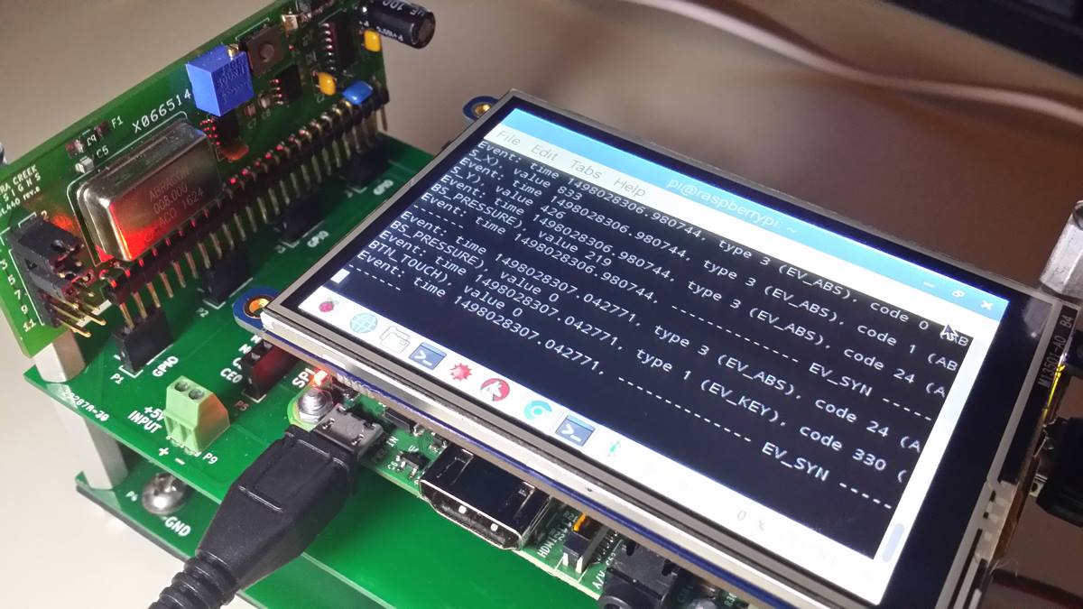
Today I finished the Linux upgrades, updates, and corresponding TFT calibration. Via puTTY and over WiFi, it took 2-days of continued remote server code query, download, transfer, extraction, and installation onto a 32GB microSD Linux O/S. No exaggeration.

This is what it took to get the monitor calibrated and aligned from a Linux Jessie config file.

Section “InputClass”
Identifier “calibration”
MatchProduct “stmpe-ts”
Option “Calibration” “150 3912 3843 255”
Option “SwapAxes” “1”
Option “InvertX” “0”
Option “InvertY” “0”
EndSection

Very pleased with the outcome of the touchscreen. Moving on to the sensor station’s schematic capture, PCB layout, and fabrication.

RPi and TFT Touchscreen Integration with Linux

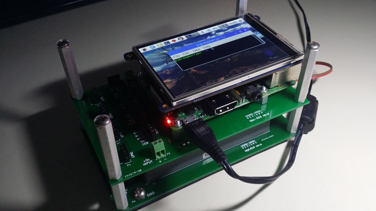
The micro slot sensor integration module continues along its path. Today I integrated the Linux operating system and TFT display onto the micro slot module base station mockup. It was a beast to get it integrated and set up. Still not fully calibrated yet.

The point is to bring an integrated touch-sensitive display onto the single board computer platform which hosts the various sensor ports and micro slot module I made just a week or so ago.

It will take tethered sensor readings and read those back to a viewer. It will provide an input path via mouse and keypad in addition to the touch screen.

Frequency Selectability Experiment with Arduino

Here is a short effort to program the control of crystal frequency output. 8MHz as the standing frequency with multipliers asserted one at a time.

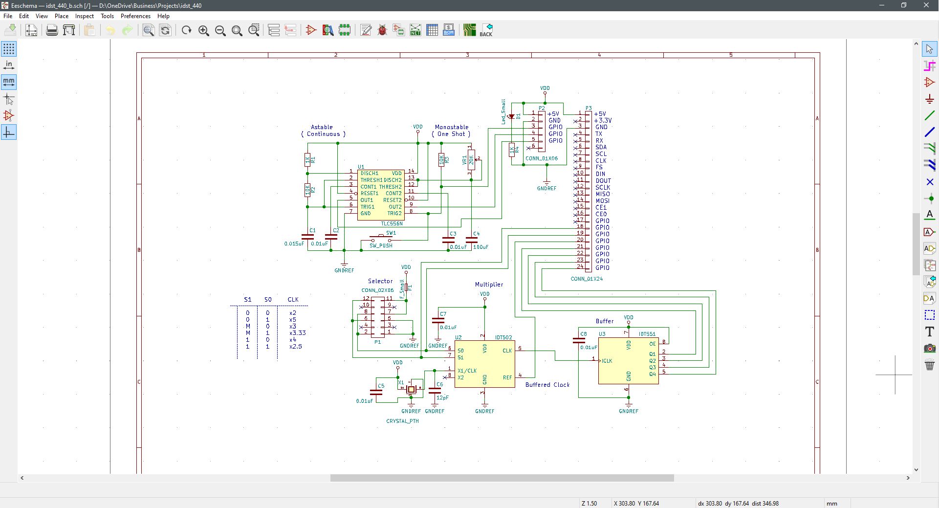
This is an experiment to encode in binary a selectable output pulse rate from a 555 timer. Where selected GPIO pins become asserted to set the desired rate. Over an Uno connection with code, I set up a user interface to push millions of pulses through to a defined output. All in a single second each instance. Staring from a single pulse rate with multipliers of 16, 20, 32, and 40. Each one separately is chosen by simply entering what a user wants over a GUI interface.


Stacked Power

This power supply generally stacks underneath all SBC modules developed and for those to follow. It is supplied through a 120VAC detachable plug-in to an isolated receptacle. The circuit breaker is protected with bottom-side fische paper to insulate against harmful voltages. The module produces a +/-15V (500mA) and +5V output at 3A. +5V for digital logic module support. +/-15V for analog line level module support.

No power switch, just plug in and go.


RPi Shield

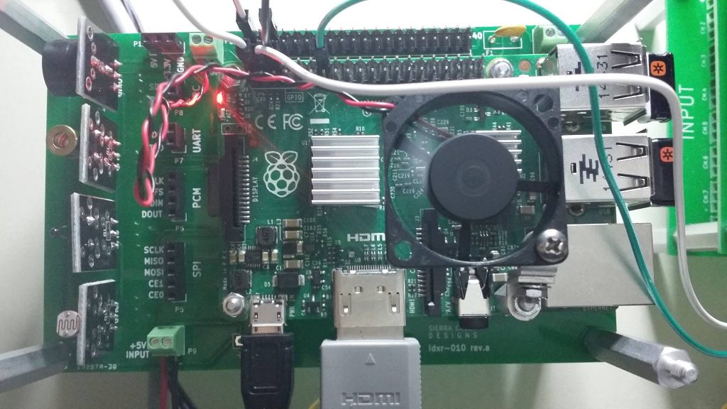
idXR.010 specifications served up. Deeply satisfying making these technologies. This time I made a break out assembly for a Raspberry Pi 2. Also with the same footprint as the Raspberry Pi 3. There will probably be a second revision of the PCB to enlarge some holes and remove or re-position a port.

Arduino to RPi Code Origination, Conversion & Test

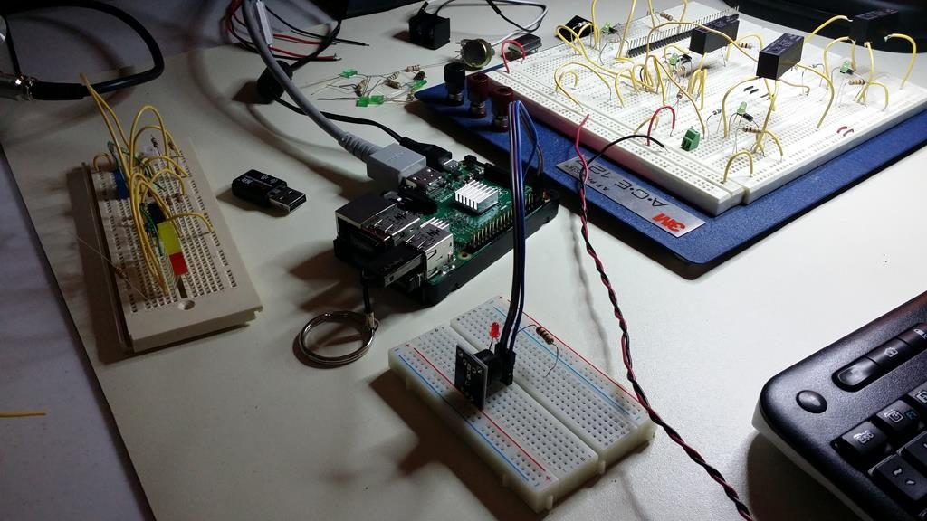
Tonight’s successful concept test with Python conversion from Arduino to Raspberry Pi. Happened to find the experimental Arduino code to drive an external sensor module. For it to behave as it should and provide acknowledgment and function as expected. It is often better to work with Arduino with available analog ports as compared to RPi with only digital ports.

This exercise served as an example of how to port code over from one platform to another. With necessary and simple edits unique from each area of operation.

Micro-Slot Build of Physical Timer Prototype

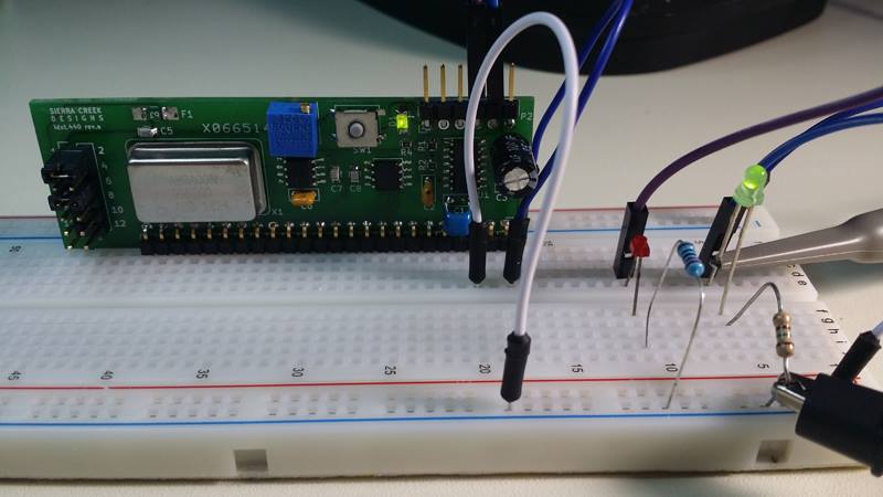
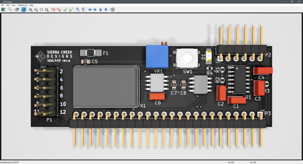
Completed first build of revision A. The new PCB fabrication company turns out okay so far. Comes from the U.S., less money and faster delivery. I still have to debug the hardware and look for flaws. Initial tests show functionality, but there are component values that probably need attention. Plus the need for a jump or two.

The blue trim control is for duty cycle variable control and the momentary switch-button sends a one-shot pulse to the output header. The second pass will be with an Arduino SBC to control its output clock speed.

Micro slot module test and debug.

Prototype Micro-Slot Module & Proof of Concept

Unraveling nested nodes to get the prototype unit fabricated and built. It’s inevitable, jumps and via’s shall be sprinkled throughout to overcome the entanglements. This is the first micro slot module among others to follow. A sort of proof of concept to arrange a vertically mounted assembly that inserts into base station modules that host SBCs.

Suitable for socketed on perforated boards as well to accommodate prototyping or one-and-done projects. The idea is to set a template project for modules overall whereas time to completion is accelerated from idea to development and completion. The framework by which originated or reference design materials is dropped-in to become far easier to implement with more attention placed upon interface or code requirements to satisfy intended functions.


Programmable Pulse Timer Concept & Design

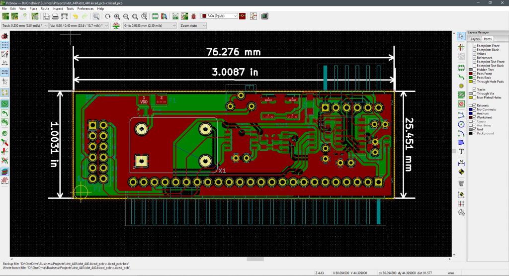
As more circuit builds come about, they’re increasing in density. Bought the parts. Gerber files, drill codes and netlist off to the fabrication house now. The programmable timing module design is finished. With hardware debugging ahead a few minor adjustments are expected once results are validated. This is a mixed-mode project where both plated through-hole and surface mount components are applied.

In a micro-slot format, this is a module intended for use in a free-standing application. With pulse speed and duty cycle setting completed manually via jumpers and a trimmer, separate outputs are assigned to independent and isolated pins at the micro-slot header.

Here is a tentative sketch of what it looks like.


RPi Sensor Station Prototype Evaluation and Debug

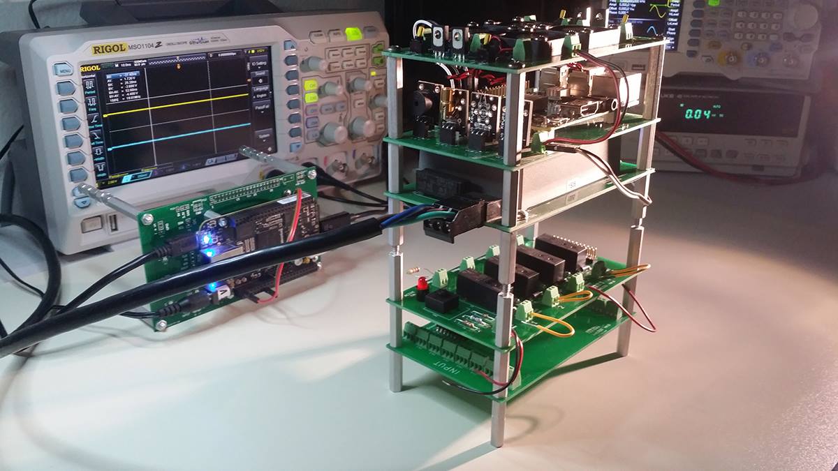
Today I finished the RPi 3 shield station prototype. Designed it, built it and the system works right from power-up. All the sensors were loaded and came online. The unit was booted with the Linux prompt to support the code for various sensors. The station is also driving each separate module developed so far as well. It’s also network aware at this location’s WiFi.

At some point, there will be a separate Arduino version of the station, but next up is the ‘universal’ power supply. Then the cooling module, and on over to additional planned modules for integration. 


LED Illumination Control with Arduino Uno

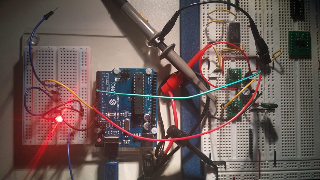
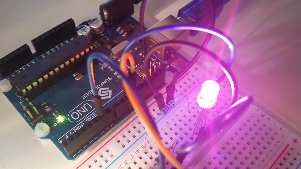
There was an online guide that walks a viewer through how to assign color variable values in code to red, green and blue. To combine each as having relative color strength to produce a mixed color output on an RGB LED. This is a way to prepare unique light color values beyond the conventional LED lights with fixed colors. In this small project, color is programmed within the Arduino IDE and thereafter code loaded into the SBC itself to run the unique color mix.

The code to set up this functionality is set up on Arduino Sketch. To write and edit instructions that determine the operability and behavioral properties of the hardware and circuit.
After declarations and set up, this is what the code looks like.

void loop()
{
Serial.println(“Please input your color choice (red, green or blue): “);
while (Serial.available()==0) {

colorChoice= Serial.readString();

if (colorChoice==”red”)
{analogWrite(redPin,brightness);
analogWrite(bluePin,0);
analogWrite(greenPin,0);
}
if (colorChoice==”green”){
analogWrite(redPin,0);
analogWrite(bluePin,0);
analogWrite(greenPin,brightness);
}
if (colorChoice==”blue”){
analogWrite(redPin,0);
analogWrite(bluePin,brightness);
analogWrite(greenPin,0);
}
if ( colorChoice != “red” && colorChoice != “green” && colorChoice != “blue”) { //test for valid input
Serial.println(“”);
Serial.println(“You have not entered a valid color, please enter red, blue or green”);
Serial.println(“”);
}
}
Power Supply Assembly for SBC Modules

Here is the power supply I made from scratch to support the various modules developed so far. With more to come, this unit is sure to prove useful again and again. A fundamental layer module for various units that are developed; both analog and digital.

This is a power supply module with +/- 15V and +5V output ports. The module hosts a low-profile switching power supply (SPS) soldered and bolted in place for high board retention. At the output of the module is a screw-locking terminal strip for each available voltage point. To include reference designators as printed on the circuit board for ease of identification and termination. The power LED illuminates as an AC input voltage is applied.

An AC source voltage is supported with a male 3-point plug-detachable receptacle for a 115VAC 60Hz input. This unit comes with a matching male plug for safe and fully insulated AC connectivity. The module is fitted with a 3A circuit breaker that provides added protection between the SPS and its source.