Archive | Research RSS feed for this section

ESP8266 NodeMCU Host Experiment

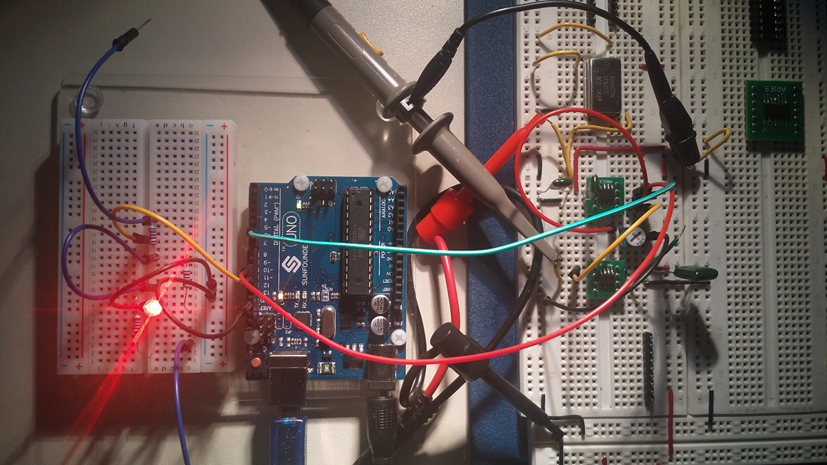
While experimenting with an ESP8266 module, I constructed a project with a photocell sensor that fed illumination data (resistance changes) over WIFI to a PC laptop browser. To accomplish this, it was necessary to build the circuit with all relevant and necessary connections with a 3.3VDC supply. The project was to monitor illumination level changes and report those over WIFI to a browser.

The experiment accomplished several objectives:

  1. Become closely familiar with the capabilities of the ESP8266 NodeMCU module.
  2. Understand its limitations, features, and Arduino support.
  3. Run code loading, Sketch edits, and operation to the ESP8266.
  4. Log in, run the program, confirm reliability and performance.

In addition to running this project, it occurred to me that it should become possible to run an external relay from an 8266 GPIO output. Simply to represent a separately powered device yet controlled by the 8266 module as it functions as a node of edge component. A component specifically as a sensor, actuator, motor, solenoid, and so forth to accompany the 8266 module.

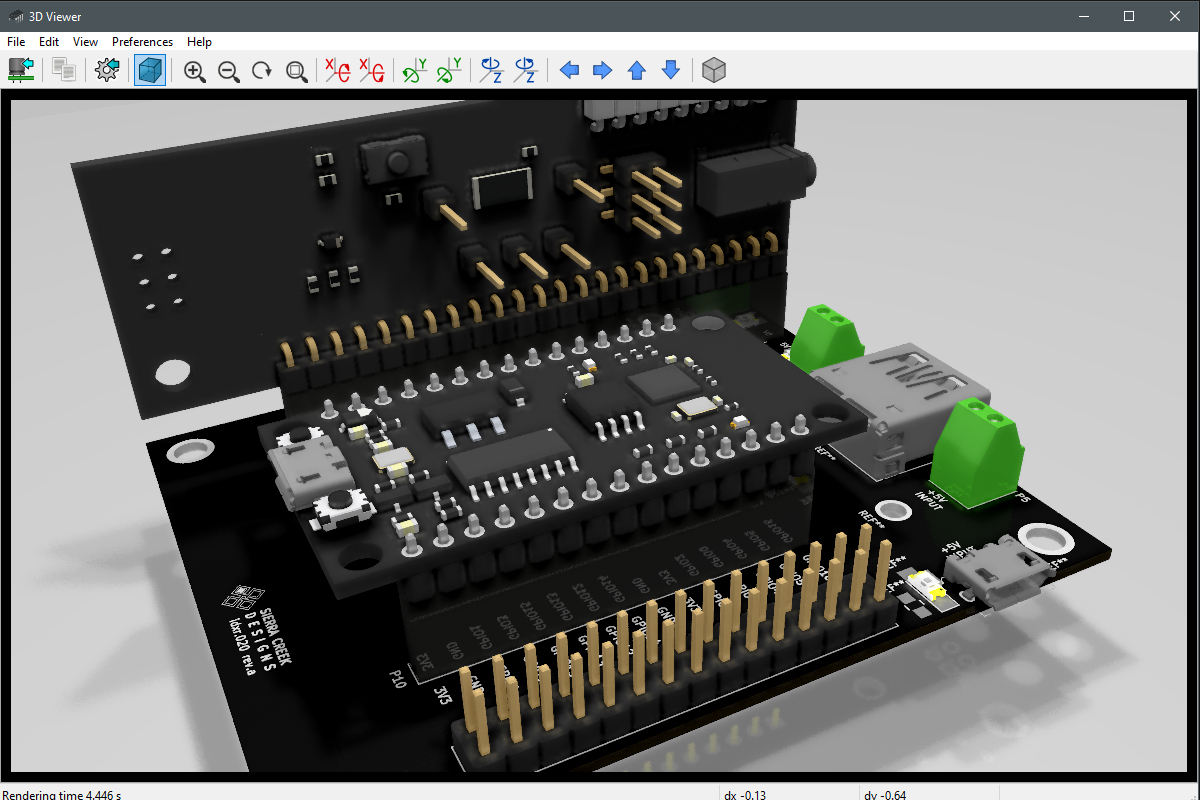
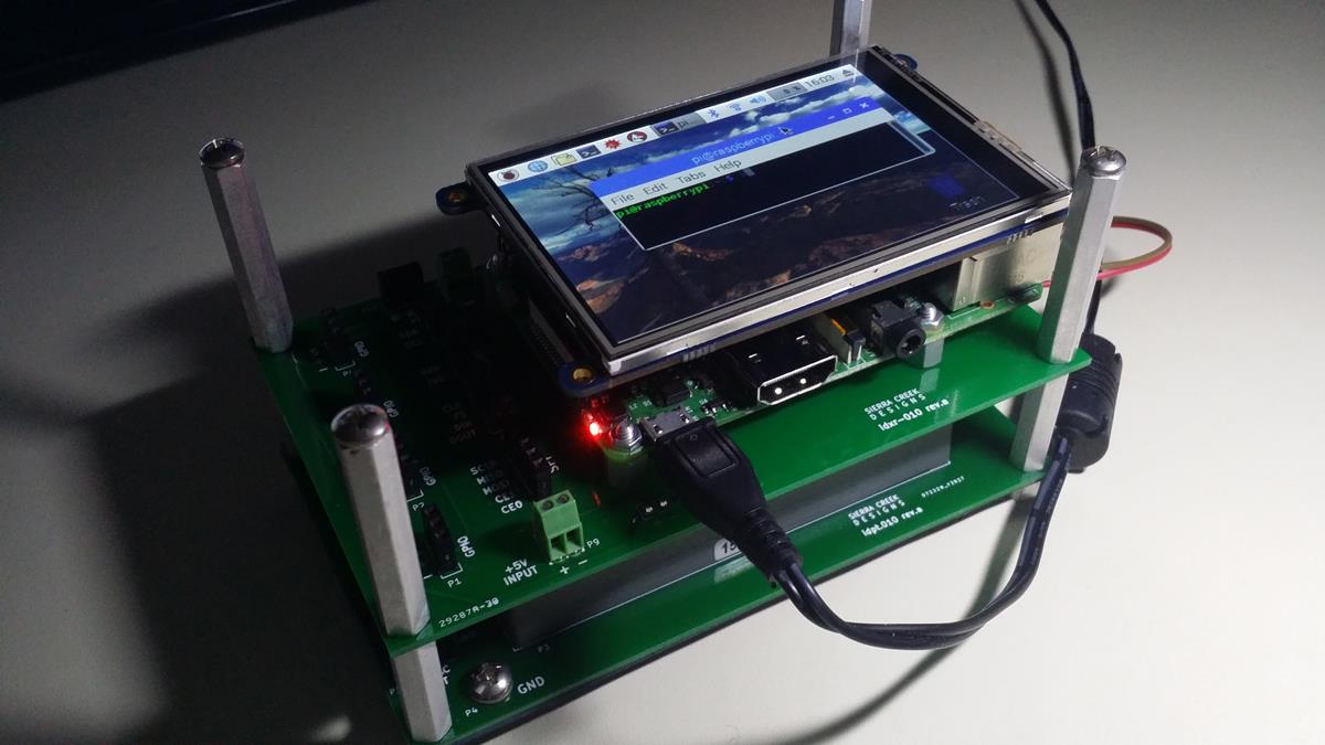
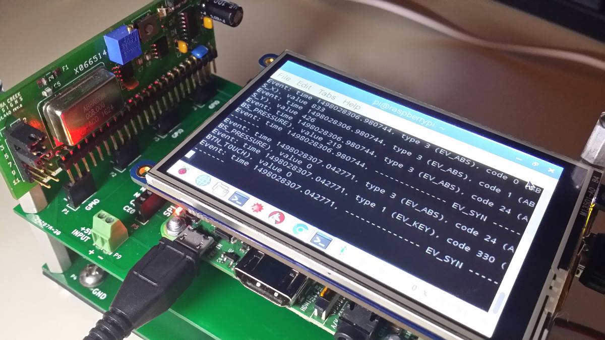
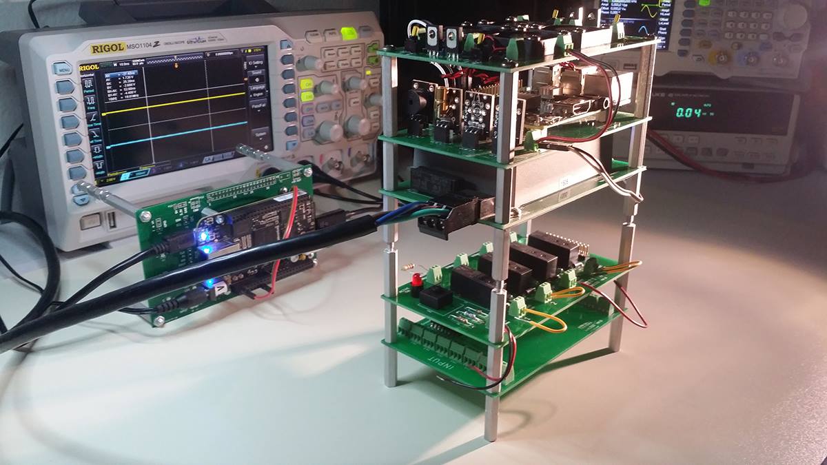
So to hash out a project that serves as a platform for new development, I put together a criterion that helps to guide a repeatable build. This is a project that hosts both an 8266 module plus a micro slot module with a regulated supply.

Project Prototype | Edge/Node Host

  • WiFi Network Capability
  • Bluetooth Capability
  • Single Point Power Supply – Input
  • Power LED
  • Single Auxiliary Power Supply – Output
  • Micro slot Port
  • Source: Regulator 5VDC for Unit
  • Source: Regulator 3V3DC for ESP8266 stepdown from 5VDC
  • External 30-pin port to ESP8266
  • Analog Sensor Interface
  • Digital Sensor Interface
  • Small Footprint 3.0″ x 2.5″

Base / Local Server

  • Laptop
  • GUI
  • Desktop
  • Mobile App

Functional Support

  • Micro slot Variable
  • Sensor Analog & Digital
  • Actuators
  • Motors & Servos
  • Solenoids, Pistons
  • Detectors


Project March

The micro-fan project is done. The march to another one continues. Once templates are set among various project elements such as BOMs, CAD files, libraries, account settings, etc., the rest comes easier project after project.


Stackable Modularity & Support of SBC Functions

This is the thermal management module stacked upon other free-standing modules. Each module that operates on its own, or together in an integrated fashion. With a small SBC based micro tower computer built from scratch (RPi), power, cooling, processing, sensor adaptation, and load control all integrated together perform functions in a stackable format.

These modules are interchangeable in terms of position and somewhat by function. There is a functional modularity that extends to other modules built together or separated to deliver isolated capabilities unique to various use-cases. Namely, cooling functionality, power support, and programmability with sensor integration. Other functions associated with common SBCs with GPIO ports include relays, actuators, sensors, drivers, routers, etc.


Harmonic Difficulties With High-Speed Clock

Here I am chasing harmonics to drain them to ground. Literally. This is what I spent time doing today. Set up a draft schematic by happenstance with a strong drink, sunglasses, and music too loud.

See that square wave on the scope? That’s exactly what’s supposed to happen given by the drawing. Only, the waveform is somewhat messy. Too many long leads, unstable harmonics, spurious noises, and other monkey business artifacts going on.

On one hand, it is completely unclear what the specific contributing causes are. Yet, on the other hand, it’s perfectly clear what likely needs the most attention in terms of clean up and the use of the specified reference design’s filters. I can see what’s on the other side before the trial concept is finished.

Voltage Controlled Oscillator Correction & Substitution

Well. It turns out that I ordered an XO crystal and not a VCXO crystal to build the design and prototype of the timing module. So retreated and went for both SMD and PTH to get things going. Probably play it safe with PTH (plated through-hole) to get things back on track.

Sort of a big deal and I’ll have to put my attention on the 556 one-shot and 1-second centered pulse with variability. It will probably take a week to get the VCXO. If I expect to have a continuous pulse supply from a single rail voltage, I must use a VCXO.

RPi and TFT Touchscreen Set Up, Programming & Calibration

Today I finished the Linux upgrades, updates, and corresponding TFT calibration. Via puTTY and over WiFi, it took 2-days of continued remote server code query, download, transfer, extraction, and installation onto a 32GB microSD Linux O/S. No exaggeration.

This is what it took to get the monitor calibrated and aligned from a Linux Jessie config file.

Section “InputClass”
Identifier “calibration”
MatchProduct “stmpe-ts”
Option “Calibration” “150 3912 3843 255”
Option “SwapAxes” “1”
Option “InvertX” “0”
Option “InvertY” “0”
EndSection

Very pleased with the outcome of the touchscreen. Moving on to the sensor station’s schematic capture, PCB layout, and fabrication.

RPi and TFT Touchscreen Integration with Linux

The micro slot sensor integration module continues along its path. Today I integrated the Linux operating system and TFT display onto the micro slot module base station mockup. It was a beast to get it integrated and set up. Still not fully calibrated yet.

The point is to bring an integrated touch-sensitive display onto the single board computer platform which hosts the various sensor ports and micro slot module I made just a week or so ago.

It will take tethered sensor readings and read those back to a viewer. It will provide an input path via mouse and keypad in addition to the touch screen.

Frequency Selectability Experiment with Arduino

Here is a short effort to program the control of crystal frequency output. 8MHz as the standing frequency with multipliers asserted one at a time.

This is an experiment to encode in binary a selectable output pulse rate from a 555 timer. Where selected GPIO pins become asserted to set the desired rate. Over an Uno connection with code, I set up a user interface to push millions of pulses through to a defined output. All in a single second each instance. Staring from a single pulse rate with multipliers of 16, 20, 32, and 40. Each one separately is chosen by simply entering what a user wants over a GUI interface.


Stacked Power

This power supply generally stacks underneath all SBC modules developed and for those to follow. It is supplied through a 120VAC detachable plug-in to an isolated receptacle. The circuit breaker is protected with bottom-side fische paper to insulate against harmful voltages. The module produces a +/-15V (500mA) and +5V output at 3A. +5V for digital logic module support. +/-15V for analog line level module support.

No power switch, just plug in and go.


RPi Shield

idXR.010 specifications served up. Deeply satisfying making these technologies. This time I made a break out assembly for a Raspberry Pi 2. Also with the same footprint as the Raspberry Pi 3. There will probably be a second revision of the PCB to enlarge some holes and remove or re-position a port.

Arduino to RPi Code Origination, Conversion & Test

Tonight’s successful concept test with Python conversion from Arduino to Raspberry Pi. Happened to find the experimental Arduino code to drive an external sensor module. For it to behave as it should and provide acknowledgment and function as expected. It is often better to work with Arduino with available analog ports as compared to RPi with only digital ports.

This exercise served as an example of how to port code over from one platform to another. With necessary and simple edits unique from each area of operation.

Micro-Slot Build of Physical Timer Prototype

Completed first build of revision A. The new PCB fabrication company turns out okay so far. Comes from the U.S., less money and faster delivery. I still have to debug the hardware and look for flaws. Initial tests show functionality, but there are component values that probably need attention. Plus the need for a jump or two.

The blue trim control is for duty cycle variable control and the momentary switch-button sends a one-shot pulse to the output header. The second pass will be with an Arduino SBC to control its output clock speed.

Micro slot module test and debug.