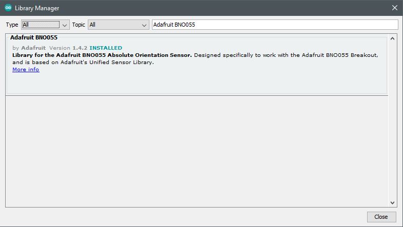
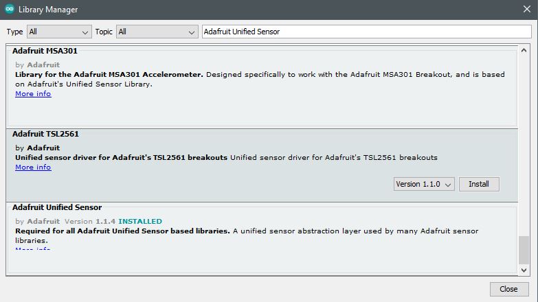
Once initial hardware is in place, it is necessary to gather the libraries to run the software and get connectivity and begin gathering the Arduino unit and the BNO055 IMU Fusion module data. In this setup, various libraries are needed to run the code as it becomes developed in this post and further along among projects.
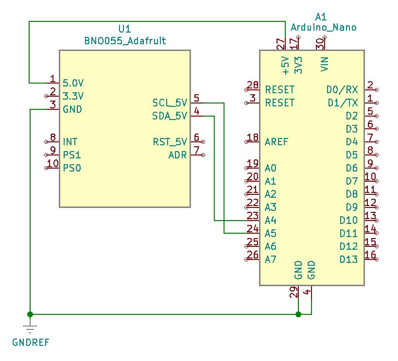
Project Schematic:
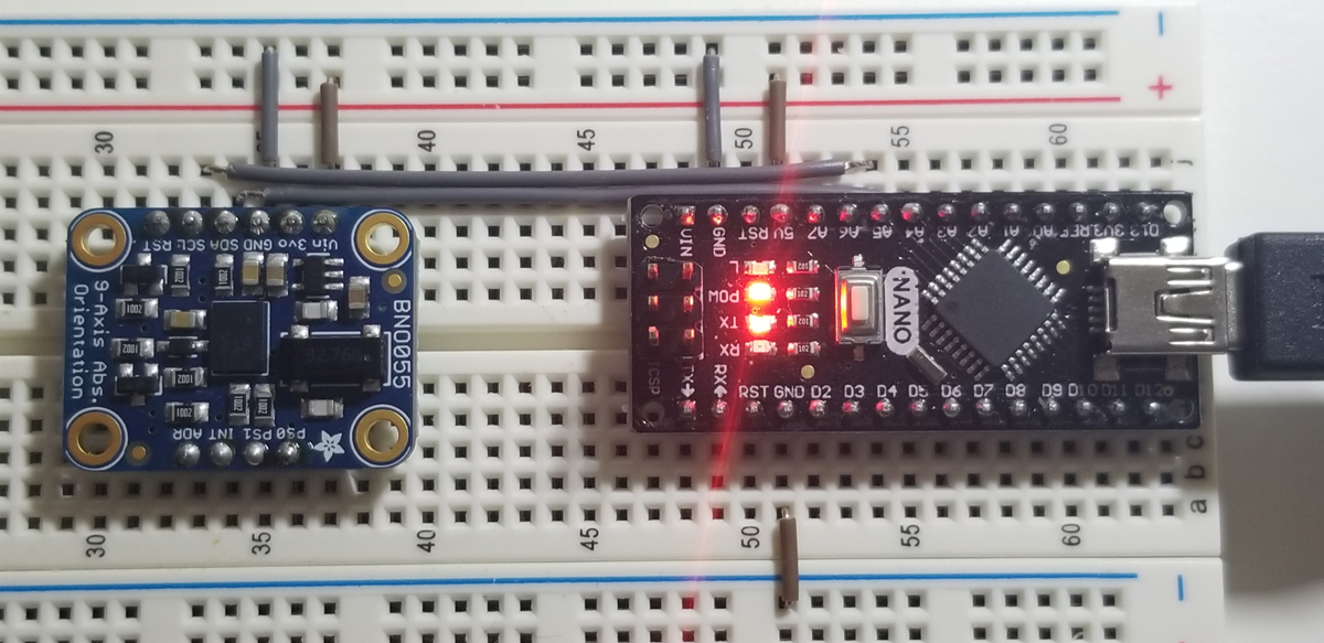
The physical build of the IMU assembly is very simple. Wiring between the IMU module and the Arduino Nano is as illustrated in the schematic below.
BNO055 Module:
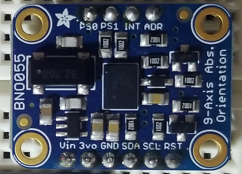
The pins on the BNO055 are laterally interspersed by function. Namely, Power, I2C, and Utility. With VIN, 3VO, and Ground as the power input pins, the SDA (serial-data) and SCL (serial clock) are the I2C pins, and finally a mix of addressing, interrupt and mode pins (RST, INT, ADR, & PS0/PS1).
BNO055 Pinout:
| Pin | Name | Description |
|---|---|---|
| 1 | VIN | 3.3-5.0V power supply input |
| 2 | 3VO | 3.3V output from the onboard linear voltage regulator, you can draw up to about 50mA. |
| 3 | GND | The common/GND pin for power and logic. |
| 4 | SDA | I2C data pin, connect to your microcontroller’s I2C data line. This pin can be used with 3V or 5V logic, and there’s a 10K pullup on this pin. |
| 5 | SCL | I2C data pin, connect to your microcontroller’s I2C data line. This pin can be used with 3V or 5V logic, and there’s a 10K pullup on this pin. |
| 6 | RST | Hardware reset pin. Set this pin low then high to cause a reset on the sensor. This pin is 5V safe. |
| 7 | ADR | Set this pin high to change the default I2C address for the BNO055 if you need to connect two ICs on the same I2C bus. The default address is 0x28. If this pin is connected to 3V, the address will be 0x29. |
| 8 | INT | The HW interrupt output pin, which can be configured to generate an interrupt signal when certain events occur like movement detected by the accelerometer, etc. (not currently supported in the Adafruit library, but the chip and HW are capable of generating this signal). The voltage level out is 3V. |
| 9 | PS1 | This pin can be used to change the mode of the device (it can also do HID-I2C and UART) and also is provided in case Bosch provides a firmware update at some point for the ARM Cortex M0 MCU inside the sensor. Should normally be left unconnected. |
| 10 | PS0 | This pin can be used to change the mode of the device (it can also do HID-I2C and UART) and also is provided in case Bosch provides a firmware update at some point for the ARM Cortex M0 MCU inside the sensor. Should normally be left unconnected. |
Project Review:
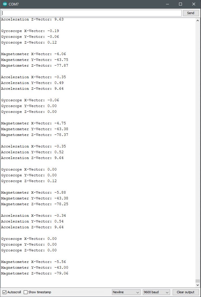
The physical movement of the IMU along the various degrees of freedom (DOF), produces vector data as demonstrated in this video. A before and after comparison of the data by a change of position indicates changes in the acceleration and gyroscope to validate positive and negative orientation.
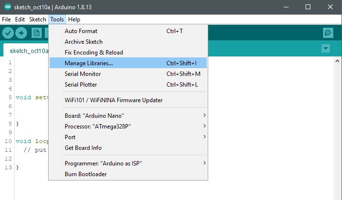
Arduino IDE:
Arduino Libraries:
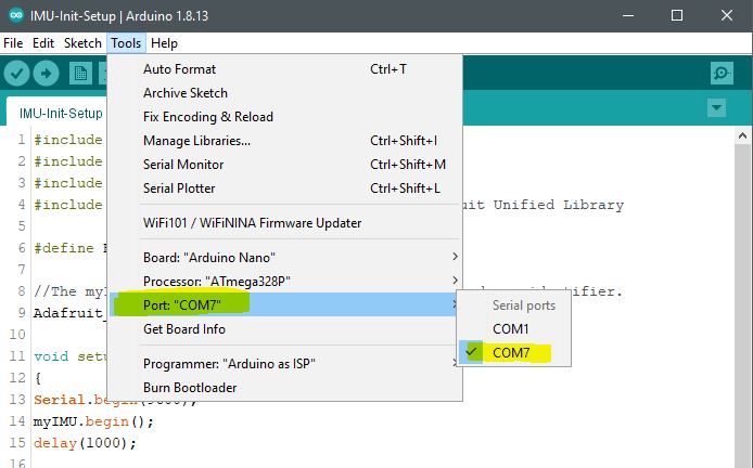
Arduino Serial Monitor:
Once a suitable serial COM port is selected from the tools menu, access to the Serial monitor is made available to call for its use in the setup code of the program (under void setup()) function as Serial.begin([baudrate]).
Select Suitable COM Port
Select Serial Monitor
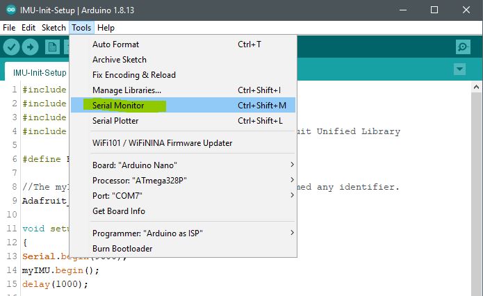
View Serial Monitor for Vector Data
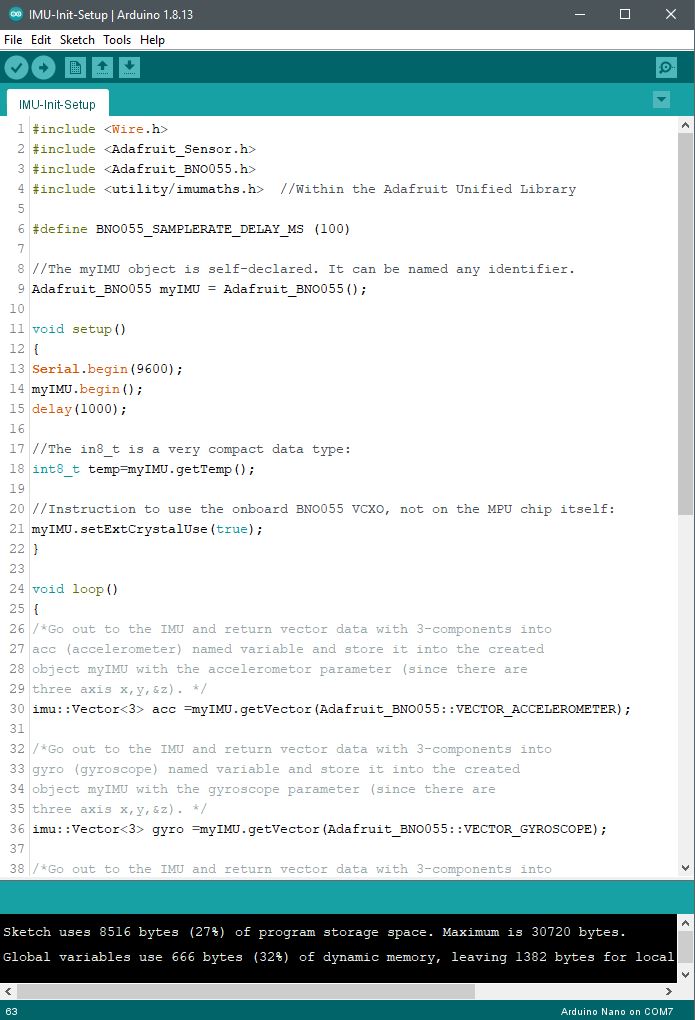
Code Example:
#include <Wire.h>
#include <Adafruit_Sensor.h>
#include <Adafruit_BNO055.h>
#include <utility/imumaths.h> //Within the Adafruit Unified Library
//The myIMU object is self-declared. It can be named any identifier.
Adafruit_BNO055 myIMU = Adafruit_BNO055();
void setup()
{
Serial.begin(9600);
myIMU.begin();
delay(1000);
//The in8_t is a very compact data type:
int8_t temp=myIMU.getTemp();
//Instruction to use the onboard BNO055 VCXO, not on the MPU chip itself:
myIMU.setExtCrystalUse(true);
}
void loop()
{
/*Go out to the IMU and return vector data with 3-components into
acc (accelerometer) named variable and store it into the created
object myIMU with the accelerometer parameter (since there are
three-axis x,y,&z). */
imu::Vector<3> acc =myIMU.getVector(Adafruit_BNO055::VECTOR_ACCELEROMETER);
/*Go out to the IMU and return vector data with 3-components into
gyro (gyroscope) named variable and store it into the created
object myIMU with the gyroscope parameter (since there are
three-axis x,y,&z). */
imu::Vector<3> gyro =myIMU.getVector(Adafruit_BNO055::VECTOR_GYROSCOPE);
/*Go out to the IMU and return vector data with 3-components into mag (magnetometer) named variable and store it into the created object myIMU with the magnetometer parameter (since there are three-axis x,y,&z). */
imu::Vector<3> mag =myIMU.getVector(Adafruit_BNO055::VECTOR_MAGNETOMETER);
Serial.print(“Acceleration X-Vector: “);
Serial.println(acc.x());
Serial.print(“Acceleration Y-Vector: “);
Serial.println(acc.y());
Serial.print(“Acceleration Z-Vector: “);
Serial.println(acc.z());
Serial.println(” “);
Serial.print(“Gyroscope X-Vector: “);
Serial.println(gyro.x());
Serial.print(“Gyroscope Y-Vector: “);
Serial.println(gyro.y());
Serial.print(“Gyroscope Z-Vector: “);
Serial.println(gyro.z());
Serial.println(” “);
Serial.print(“Magnetometer X-Vector: “);
Serial.println(mag.x());
Serial.print(“Magnetometer Y-Vector: “);
Serial.println(mag.y());
Serial.print(“Magnetometer Z-Vector: “);
Serial.println(mag.z());
Serial.println(” “);
/* Insert delay to assure you’re not going faster than what the sensor can handle. */
delay(BNO055_SAMPLERATE_DELAY_MS);
}


