Tag Archives | analog

Arduino to RPi Code Origination, Conversion & Test

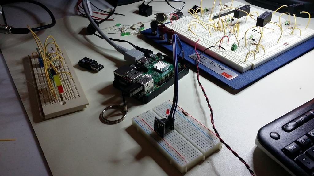
Tonight’s successful concept test with Python conversion from Arduino to Raspberry Pi. Happened to find the experimental Arduino code to drive an external sensor module. For it to behave as it should and provide acknowledgment and function as expected. It is often better to work with Arduino with available analog ports as compared to RPi with only digital ports.

This exercise served as an example of how to port code over from one platform to another. With necessary and simple edits unique from each area of operation.
Power Supply Assembly for SBC Modules

Here is the power supply I made from scratch to support the various modules developed so far. With more to come, this unit is sure to prove useful again and again. A fundamental layer module for various units that are developed; both analog and digital.

This is a power supply module with +/- 15V and +5V output ports. The module hosts a low-profile switching power supply (SPS) soldered and bolted in place for high board retention. At the output of the module is a screw-locking terminal strip for each available voltage point. To include reference designators as printed on the circuit board for ease of identification and termination. The power LED illuminates as an AC input voltage is applied.

An AC source voltage is supported with a male 3-point plug-detachable receptacle for a 115VAC 60Hz input. This unit comes with a matching male plug for safe and fully insulated AC connectivity. The module is fitted with a 3A circuit breaker that provides added protection between the SPS and its source.


4-Channel Signal Relay Board for SBC Modules

This is a video walk-through about a 4-channel contact closure relay module I made. An example application is demonstrated here by driving a micro-fan through a relay and connector signal path via a remote and physically isolated contact closure made at an input. There are many applications by which this module will prove both practical and useful.

It serves as a way to achieve a high-current path closure by simply providing a shorted connection at each input.

https://youtu.be/1FgDOD8vWGQ


Signal Interrupt & Ground Lift Board for SBC Modules

This is a video that explains the purpose and function of the signal interrupt module. This was the first module I developed and made as an effort to get familiar with KiCAD and other development instruments. It is a simple 8-channel 1:1 input to output signal interface unit that provides for signal interrupt and patch capabilities to external devices. The module also supports micro-patch capabilities from numbered input channels to differently designated channels via patch conductors and to 24-pin connector terminals.