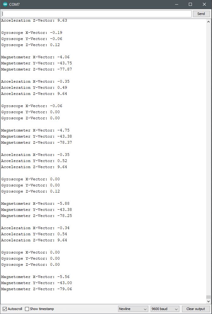
In an effort to further delve into the inner workings of the BNO055 accelerometer and its functions, the serial plotter was applied to the project. To better understand how the produced data is rendered over the I2C SDA/SCL connection to the Nano, the data is translated by the plotter into a visual char as presented below. The gyro and magneto functions of the IMU are not included in this review to get a better depth of understanding around the module’s capabilities.
The three-axis of acceleration is plotted over time as a function of latitude movement (x-axis), longitude movement (y-axis), and vertical movement (z-axis). As the IMU module is moved and oriented to different positions, the sensor interprets that activity by measurement of differences in charge. Specifically, internally charged surfaces are separated by differences in area and distance to vary a combined capacitive charge. That change in charge, as measured, corresponds to the difference in acceleration since internal plate movement varies in all three directions.
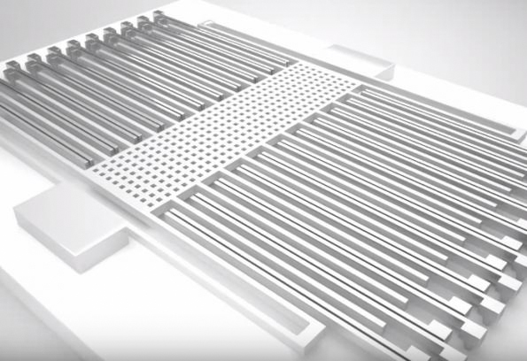
In the photo here, imagine that a lower plate is moving up and down, back and forth through its comb structure. The surface area for each direction of movement brings about a difference in capacitive charge where that becomes interpreted as acceleration. The substrate below the comb structure consists of a surface area that corresponds to the z-axis charge that is tracked for changes in vertical acceleration. The lattice framed structure is suspended by springs to assure continuous and precise movement in any direction within defined limits.
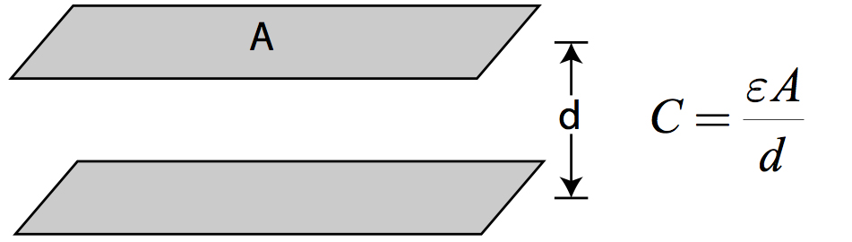
It is again useful to recognize that the amount of charge present within the capacitor, or capacitive body, is determined by the surface area and distance between two charged plates. Reduce the surface area between the two plates, and the total capacitive charge is reduced. Increase the distance between the two plates and the capacitive charge is reduced. This simplified explanation does not take into account any dielectric properties that exist among different types of capacitors.
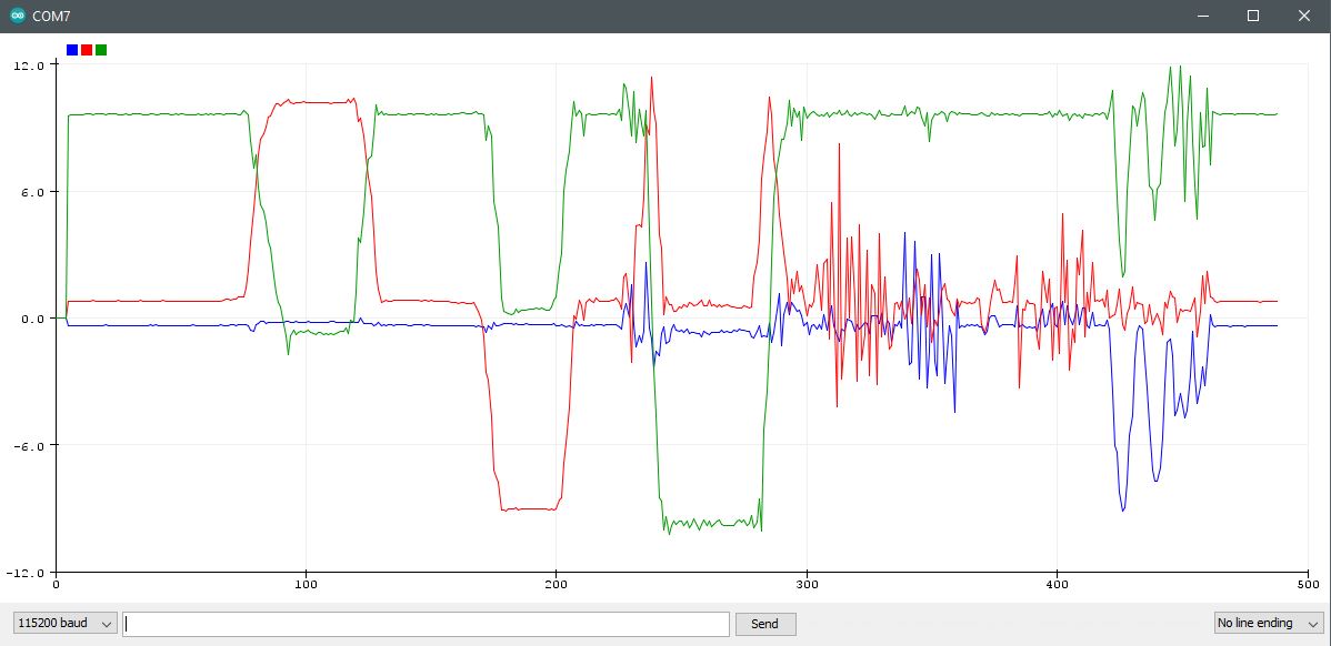
9.8m/s2 since that is the acceleration of gravity present at the IMU module. The -9.8m/s2 reading is with the IMU inverted with the internal
micro-electro-mechanical (MEM) structure pulled down by gravity.
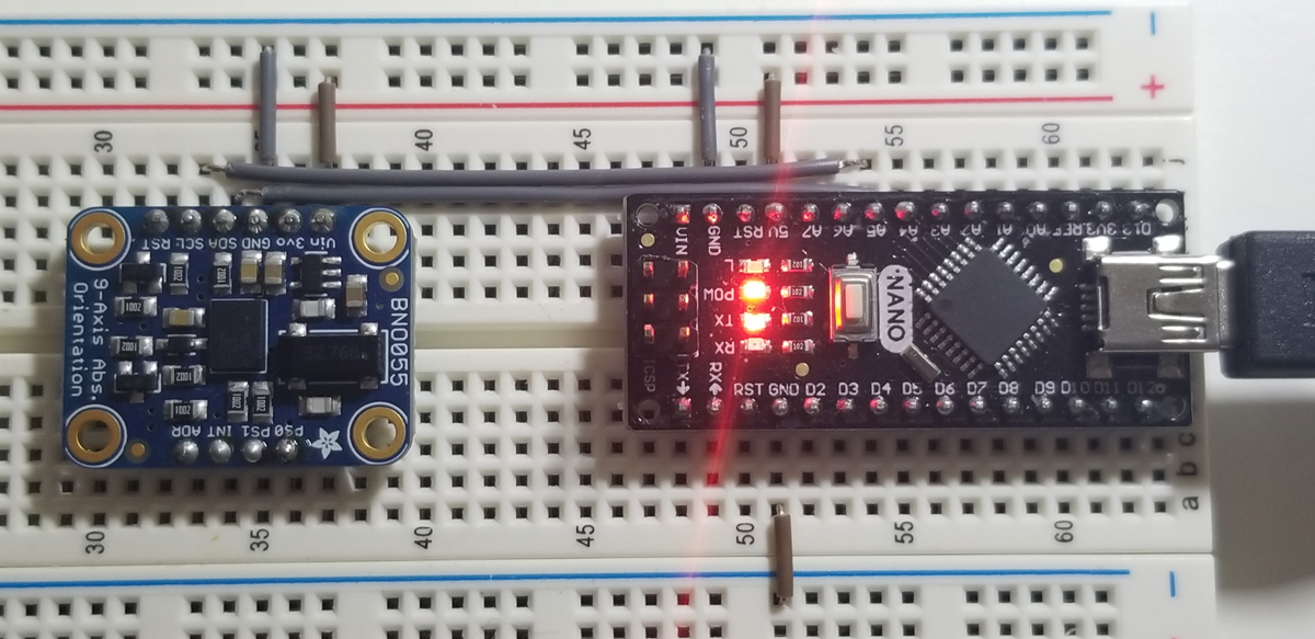
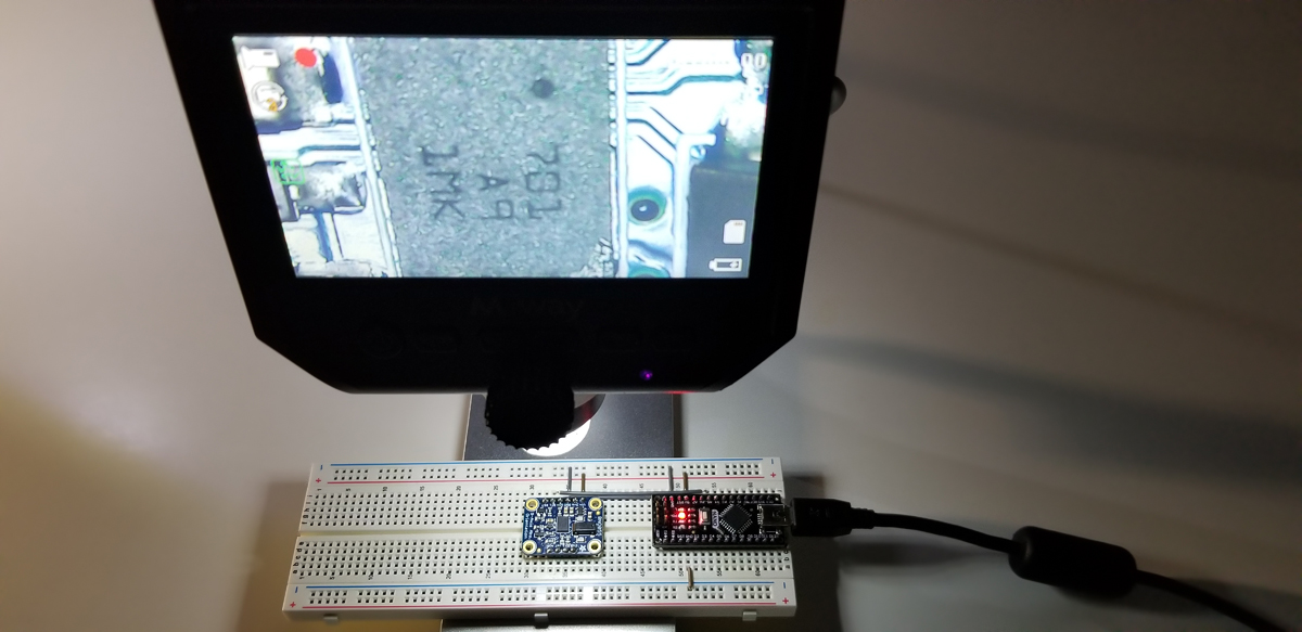
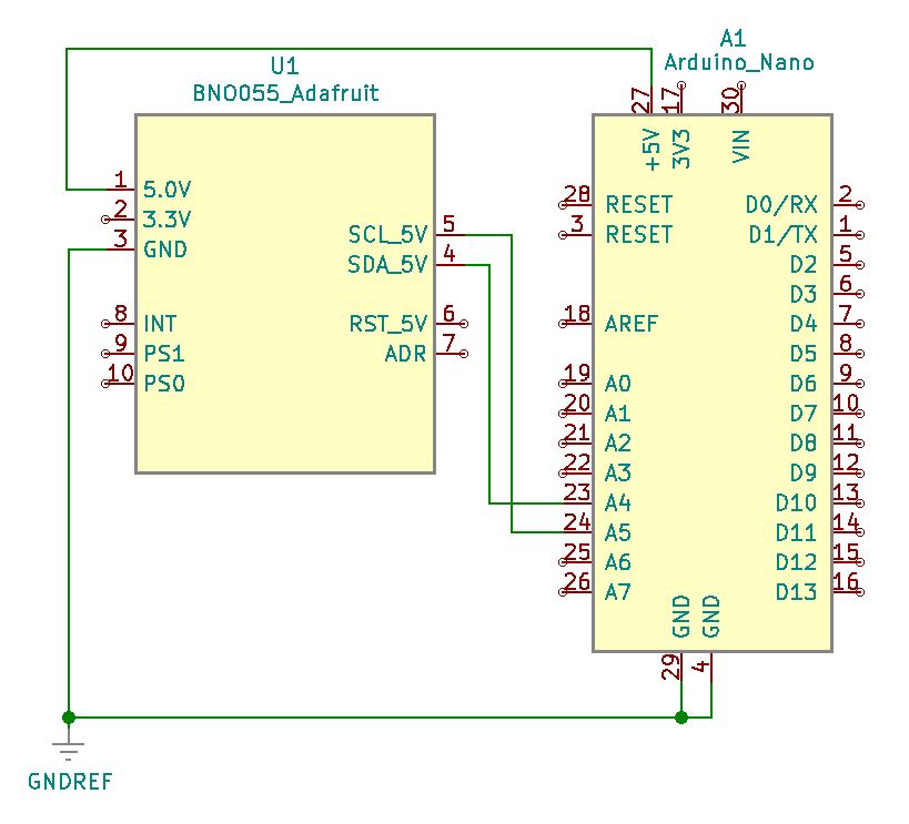
Project Schematic:
The same basic connections are in place as before in the prior set up project. The key I2C communication connections between the modules remain in place to transfer clock and data for integration and processing. Both modules share the same ground and 5V VCC.
Project Review:
As demonstrated in this video, the IMU module’s data plot extends across time as the acceleration tests are carried out. As the IMU module is moved to different positions and orientations, observe the corresponding changes in plotted graphical data.
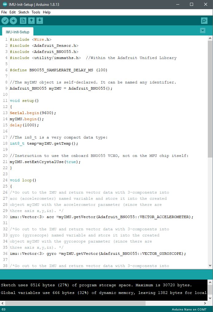
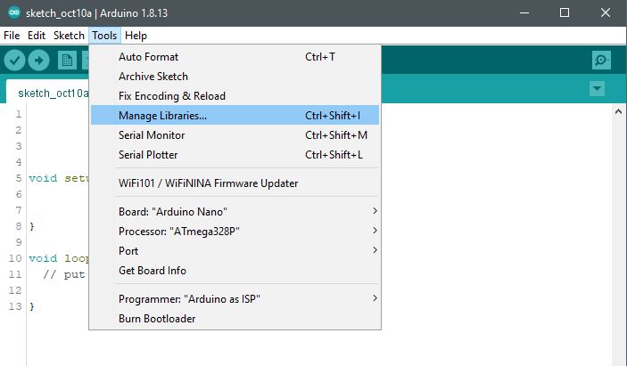
Code Example:
#include <Wire.h>
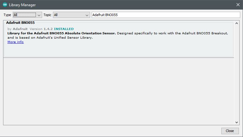
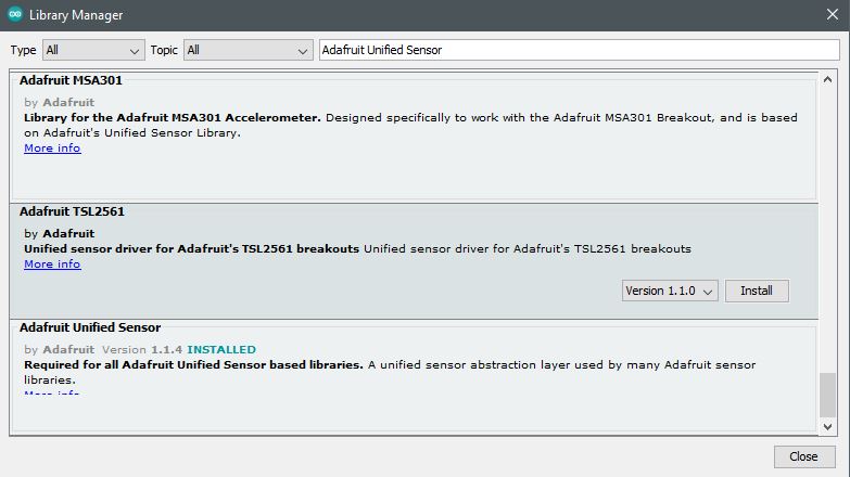
#include <Adafruit_Sensor.h>
#include <Adafruit_BNO055.h>
/* Within the Adafruit Unified Library*/
#include <utility/imumaths.h>
#define BNO055_SAMPLERATE_DELAY_MS (100)
/* The myIMU object is self-declared. It can be named any identifier.*/
Adafruit_BNO055 myIMU = Adafruit_BNO055();
void setup()
{
Serial.begin(115200);
myIMU.begin();
delay(1000);
/* The in8_t is a very compact data type:*/
int8_t temp=myIMU.getTemp();
/* Instruction to use the onboard BNO055 VCXO, not on the MPU chip itself:*/
myIMU.setExtCrystalUse(true);
}
void loop()
{
imu::Vector<3> acc =myIMU.getVector(Adafruit_BNO055::VECTOR_ACCELEROMETER);
Serial.print(acc.x());
Serial.print(“,”);
Serial.print(acc.y());
Serial.print(“,”);
Serial.println(acc.z());
/* Insert delay to assure you’re not going faster than what the sensor can handle. */
delay(BNO055_SAMPLERATE_DELAY_MS);
}