Archive | Arduino RSS feed for this section

Photoresistor Sensor Control of Buzzer Alarm

Using the point-slope formula between the on-time and off-time of a passive buzzer, we can control the high frequency and low-frequency tone sound as a function of light. As a light source is drawn near to the photoresistor, the buzzer will increase in frequency. Conversely, as the light source is moved away from the photoresistor sensor, the buzzer sound will correspond to a low-frequency tone. Removal of the light source fully separated from the photoresistor permits an ambient light reading until the buzzer is fully settled to a maximally lower frequency of sound.

By experimenting with the point-slope formula in the code, you are able to change the tonality. However, to get a precise range and audible quality of the buzzer, it is best to calculate the on-time from a sample source reading at the sensor and an off-time (delay time) to complete each frequency cycle. The more cycles of on and off time, the higher the frequency.

Simple component placement and wiring hook up.

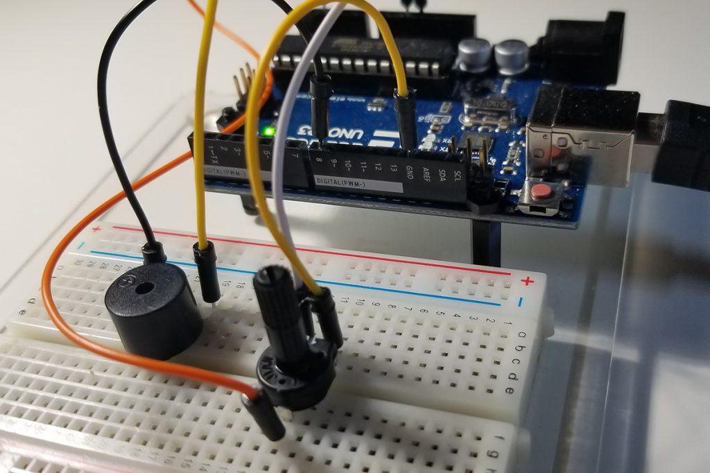
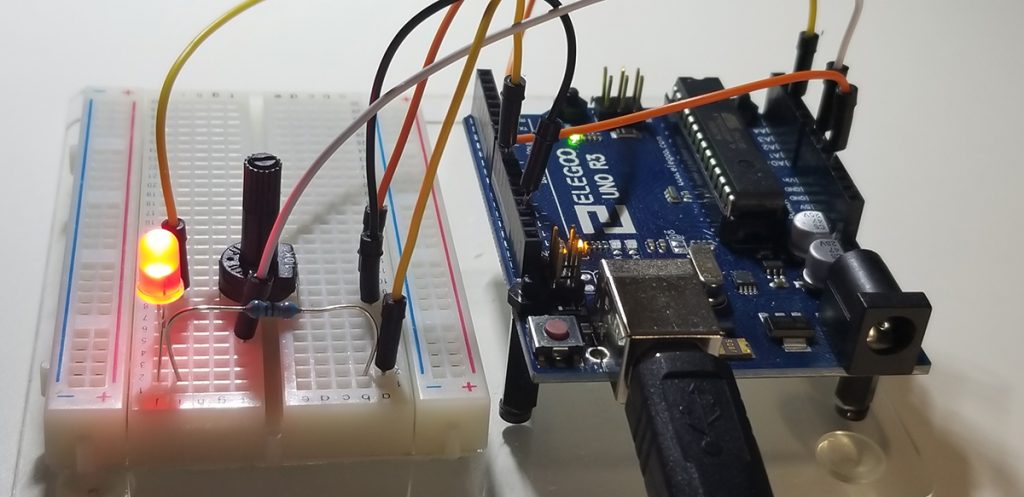
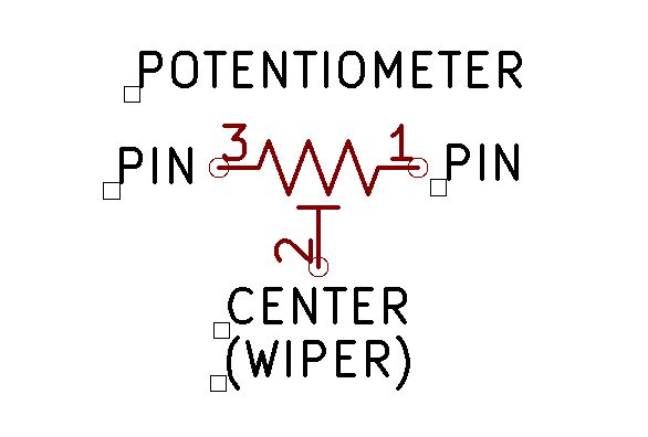
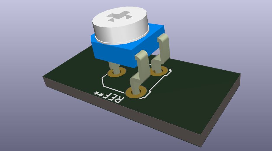
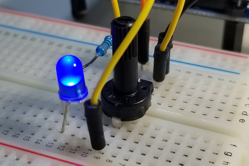
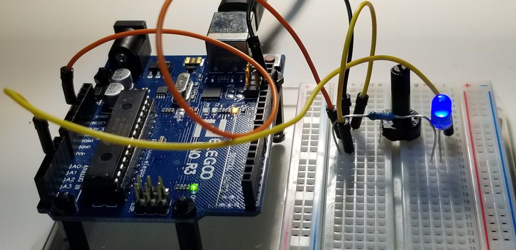
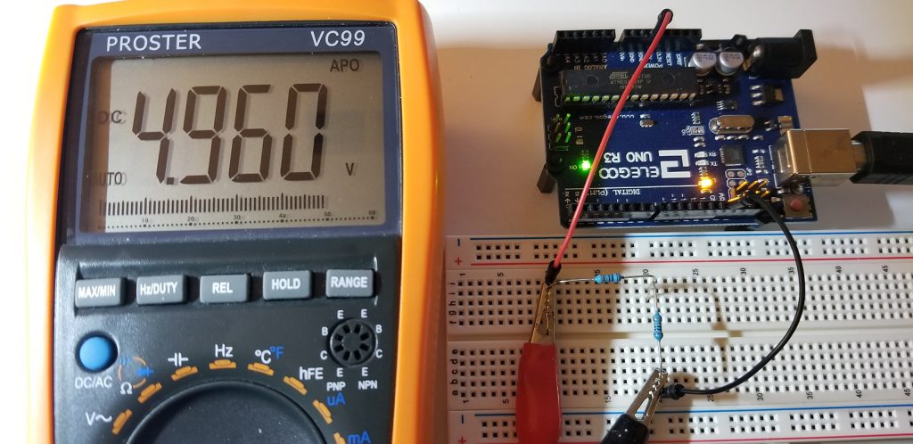
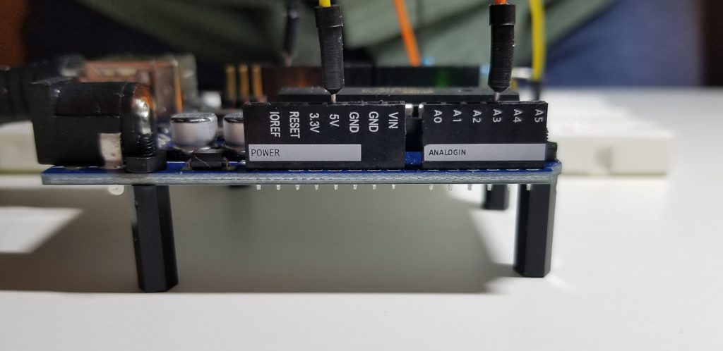
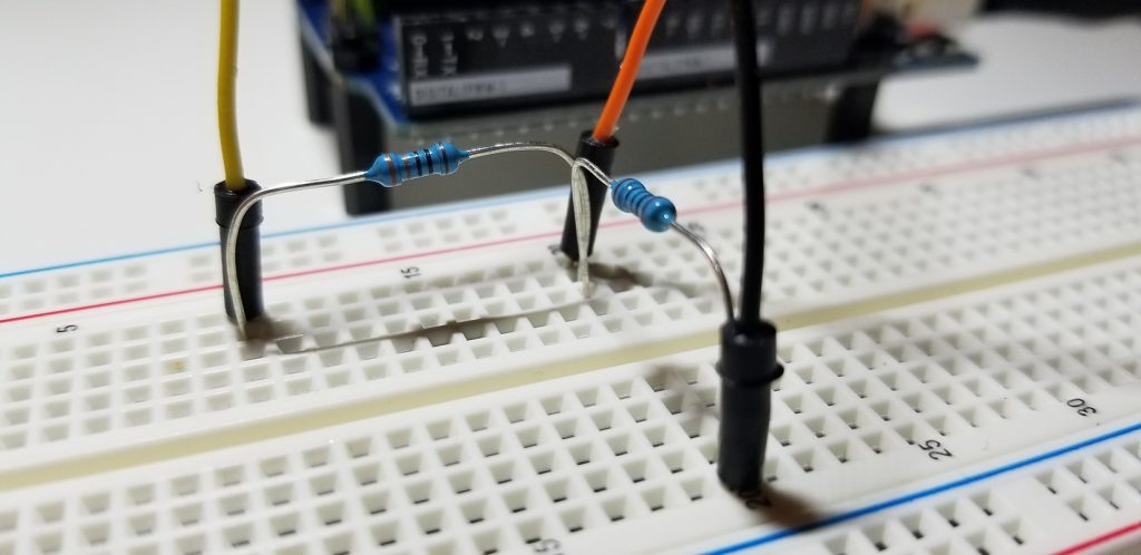
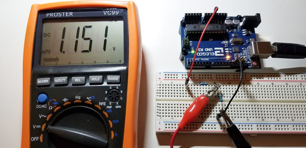
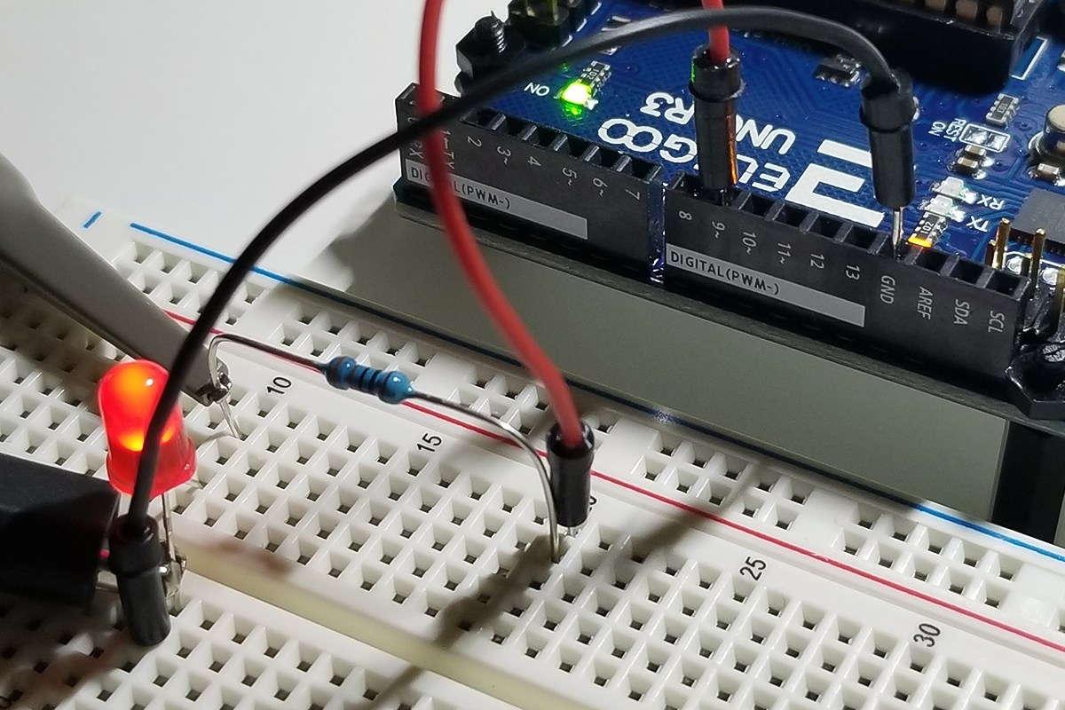
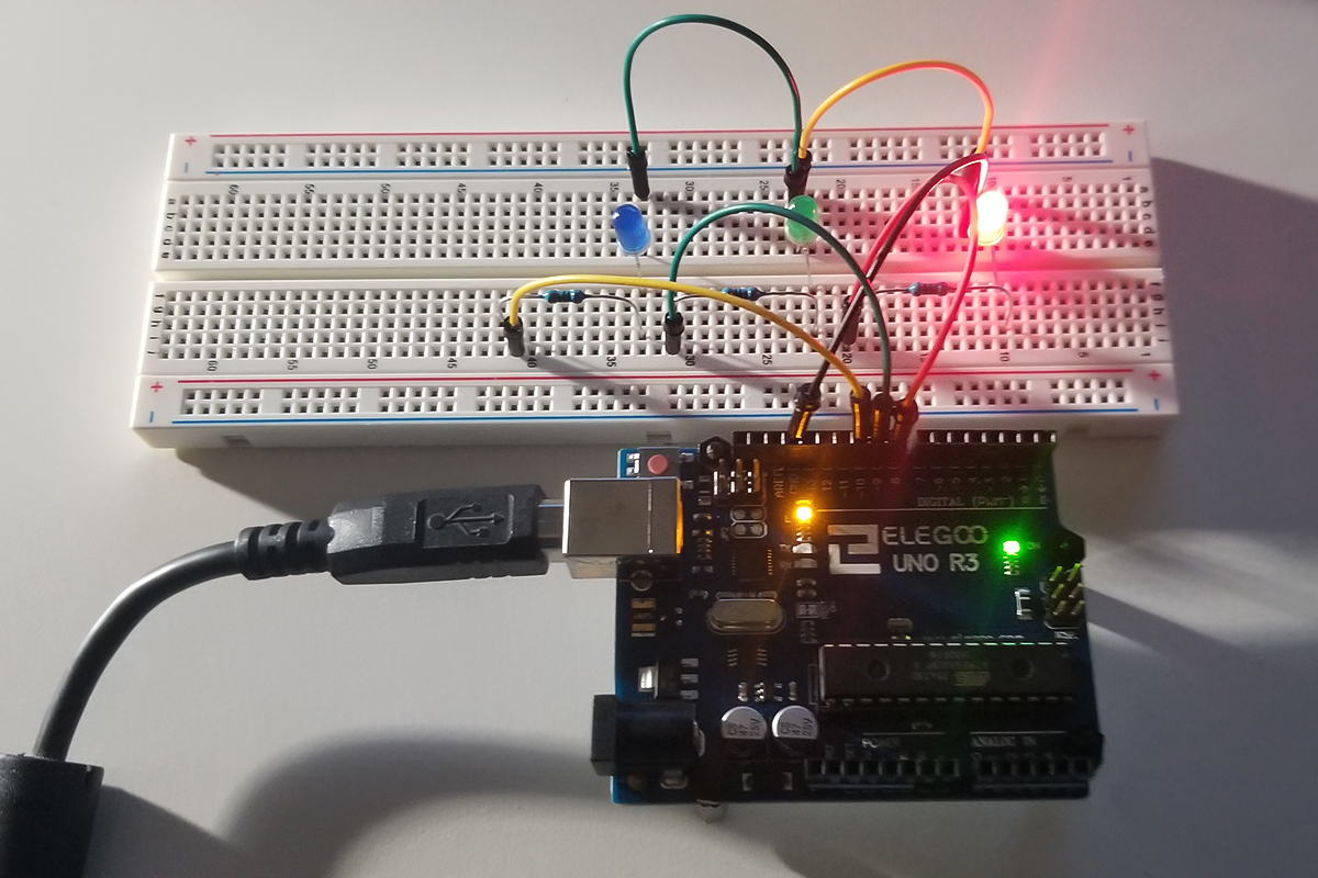
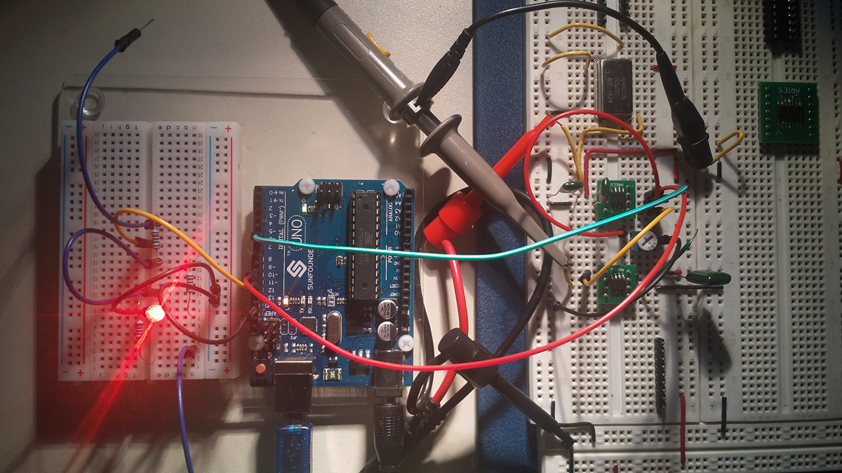
5K Resistor in series with the photoresistor sensor. The Arduino UNO pin connected between the 5K resistor and the light sensor is reading a change in voltage present at this connection. The voltage divider changes value as the resistance of the light sensor increases or decreases. As the sensor’s resistance value decreases with increasing light levels, it conducts more and drops less voltage. The analogRead code instruction detects the change of voltage at this node and in turn produces change in tonality via the digitalWrite command at the output pin connected to the buzzer.

5K-ohm resistor in series with the photoresistor sensor and passive buzzer.

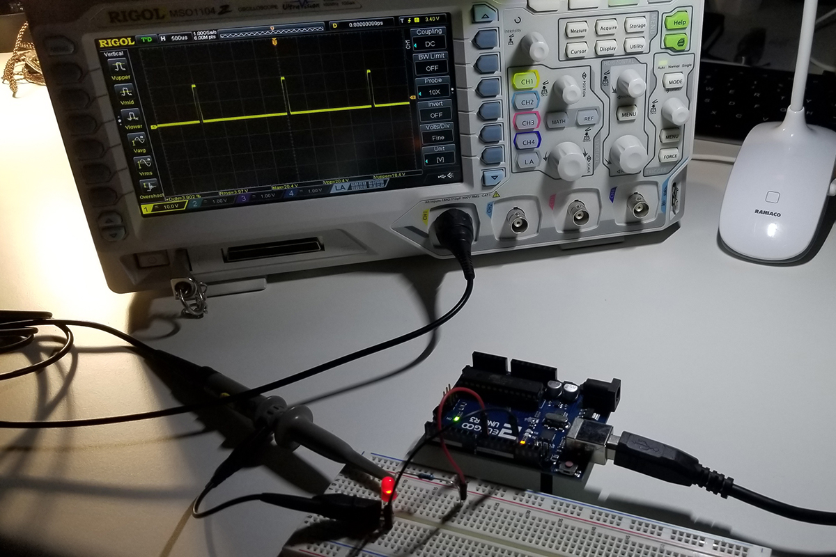
This is a passive buzzer that is driven by a voltage and light level separated by a delay between each digitalWrite event. Causing the buzzer to produce a tone of lower or greater frequency as new voltages are presented to it. Each new voltage level from the voltage divider produces its sound frequency by continuously turning the buzzer on and off again as it recognizes new levels as light intensity changes.

Light Sensor and resistor voltage divider input source. With separate buzzer output termination, the Arduino UNO module serves as the processing device for control via code instructions. ( Negative polarity terminal disconnected to interrupt operation).

Program & Functional Operation

This video demonstrates a change in buzzer tone as the light source distance from the light sensor is changed. The closer to the light sensor is exposed to a higher intensity of illumination, the higher the frequency in sound. The lower the light intensity, the lower the sound pitch or frequency.


Light & Delay Value Selection

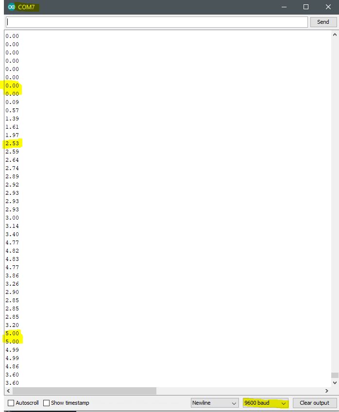
To come up with a delay value for the integer variable declared in the code, it is necessary to the light sensor’s voltage value into memory via pin A0 on the Arduino. This means it is necessary to perform a calculation on the changes of input voltage levels as they change as light illumination intensity changes. The formula derivation is as follows:
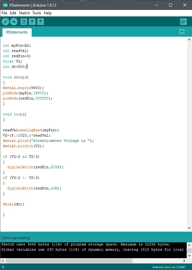
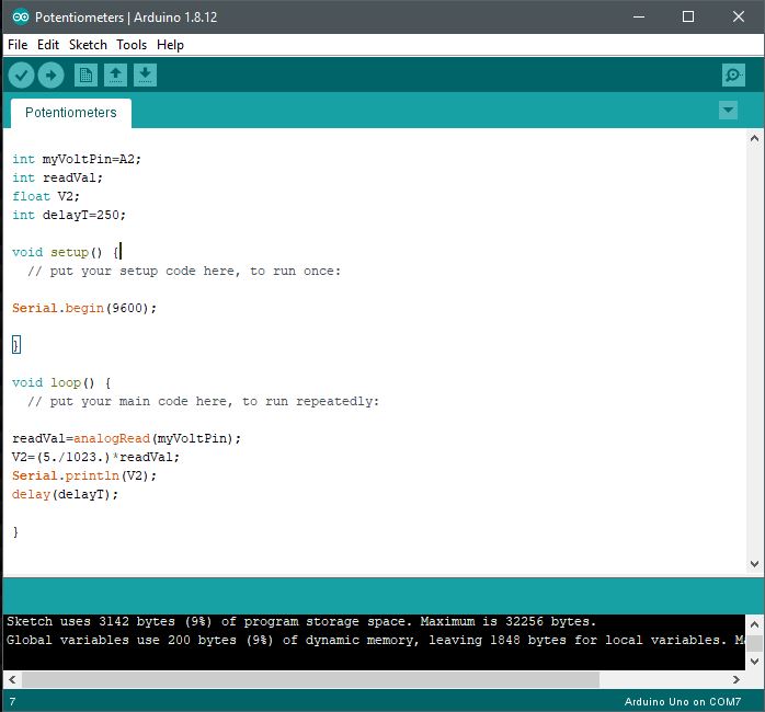
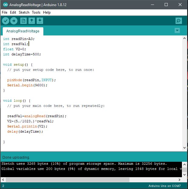
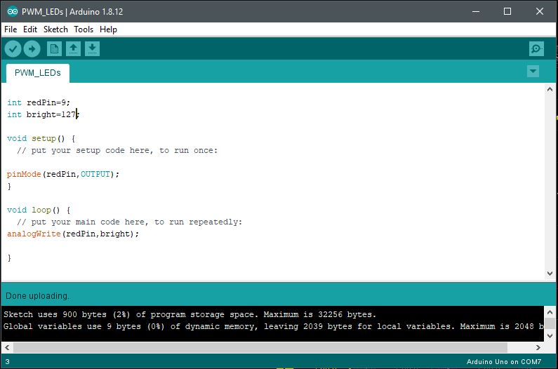
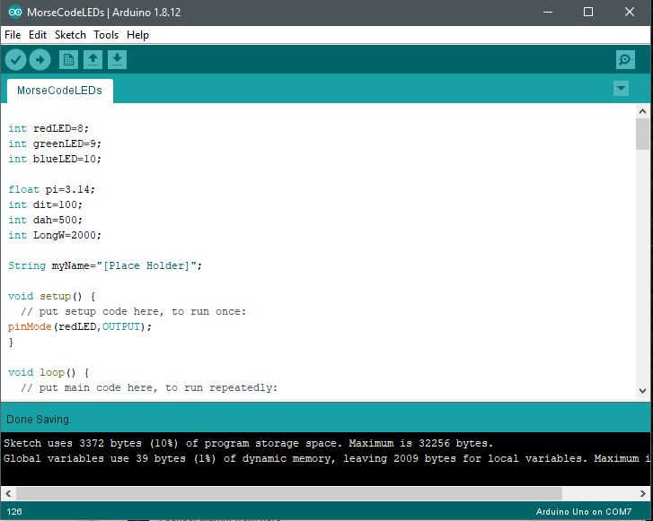
-Paul McWhorter

Code Setup:

Copy & paste this code to your Arduino Sketch as desired to edit or experiment with your program.

int lightPin=A0;
int buzzPin=8;
int lightVal;
int delayT;

void setup()

{
pinMode(A0,INPUT);
pinMode(buzzPin,OUTPUT);
Serial.begin(9600);
}

void loop()
{
lightVal=analogRead(lightPin);

//This sets the tone for the buzzer
delayT=(9./550.)lightVal-(9.200./550.)+1.;

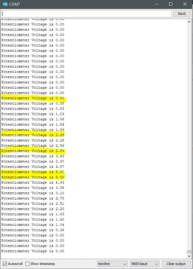
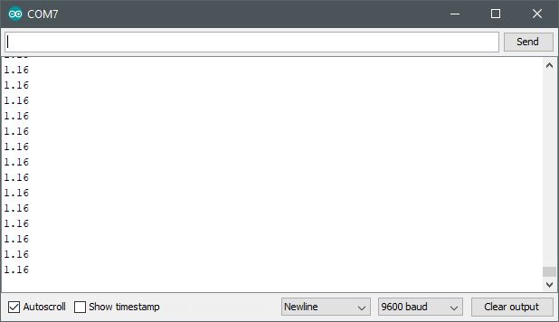
Serial.println(delayT);
digitalWrite(buzzPin,HIGH);
delay(delayT);
digitalWrite(buzzPin,LOW);
delay(delayT);

}

Arduino IDE:


Active Level Alarm with Trim Control via GPIO

This project sets up a continuously monitored voltage level change at a potentiometer as derived from a source reference. As continuously variable voltage level changes, voltage levels are read into memory from an analogRead operation. From memory, those levels are read and compared to an assigned maximum value (1000). If an increase of voltage is exceeded beyond that value (by potentiometer control), the alarm triggers with a corresponding notice within the serial monitor.

Active buzzer and potentiometer connectivity to Arduino UNO. Analog GPIO pin A3 and digital GPIO pin 8 attached to potentiometer and DC buzzer respectively. This is no a passive buzzer which requires and AC signal.
Both devices require a ground path while only the potentiometer requires its reference 5VDC. The wiper pin of the pot is connected to the A3 GPIO port.

Program & Functional Operation:

This video demonstrates how the code corresponds to the running levels that appear at the Serial Monitor. Notice the code specifies a 1000 limit to the analogRead of the potentiometer level value. Further along in the video, the potentiometer control is rotated to indicate an exceeded level until rotated back below that value again.


Code Setup:

int potVal;
int buzzPin=8;
int potPin=A3;

void setup()
{
Serial.begin(9600);
pinMode(buzzPin,OUTPUT);
pinMode(potPin,INPUT);
}

void loop()
{
potVal=analogRead(potPin);
Serial.println(potVal);
delay(400);
while (potVal>1000)
{
digitalWrite(buzzPin,HIGH);
potVal=analogRead(potPin);
Serial.println(potVal);
delay(400);
Serial.println(“Level Exceeded”);
}
digitalWrite(buzzPin,LOW);
}

Arduino IDE:

Code set up in the Arduino IDE (Sketch).
Continuously scrolled level increases or decreases as values are read into memory via analogRead from the potentiometer control.

Further Project Details: -Paul McWhorter

Conditional IF Operation with Logic Parameters

To evaluate the function and purpose of an IF statement, a true or false, or comparative operation is performed for external circuit hardware to act upon conditions or an input of some type. In this case, as a trim potentiometer control is rotated, an output voltage level changes between 0 and 5VDC at an input pin connected to the control. This pin is using an analogRead to get the changing voltage value present at the control within the circuit to perform new functions elsewhere within the Arduino UNO unit.

In this case, as the voltage level changes within the 0 to 5VDC scale, the level value is calculated within the Arduino code and displayed out onto the Arduino serial monitor. Moreover, that value is then compared to an argument, such as a maximum or minimum level, to illuminate an LED or turn it off again. The LED simply represents a circuit functions that could otherwise be something else such as a relay, actuator, solenoid, or another analog or digital function.

Hardware Setup:

Wiring of the potentiometer with LED at two separate GPIO Ports for independent control using Arduino code.
Added setup illustration to indicate connectivity.
LED indicator only illuminate when conditional statements are true. As a test condition, code checks for scaled voltage present at GPIO pin and turns on or off LED accordingly.

Code Setup:

int myPin=A2;
int readVal;
int redPin=9;
float V2;
int dt=500;

void setup()
{
Serial.begin(9600);
pinMode(myPin,INPUT);
pinMode(redPin,OUTPUT);
}

void loop()
{

readVal=analogRead(myPin);
V2=(5./1023.)*readVal;
Serial.print(“Potentiometer Voltage is “);
Serial.println(V2);

if (V2>2 && V2<3) // && –> Logical AND Operation
{
digitalWrite(redPin,HIGH);
} if (V2<2 || V2>3) // || –> Logical OR Operation
{
digitalWrite(redPin,LOW);
}


delay(dt);
}

The IF statement parameters that serve as an evaluation condition, could be simple less-than, or greater than, logic, equal-to (==), not equal-to (!=), and others by a constant or variable assignment. In this case, V2 is the value in memory that is checked while changes are made at the potentiometer controller to determine if an operating condition is true. Specifically, if the control voltage is between 2 and 3VDC, illuminate the LED. If the voltage is not between 2 and 3VDC, then turn the LED off.

Arduino IDE:

Code set up in the Arduino IDE (Sketch).
Continously scrolled voltage values presented as potentiometer wiper is rotated. To demonstrate the voltage scale and range as a function of analogRead operation.

Further Project Details: -Paul McWhorter

Voltage Control with analogRead Operation

With the use of a potentiometer (trim-pot), it is possible to control a voltage level presented to an external circuit from a reference supply voltage connected to an Arduino unit. Through the use of a trim-pot, a supply voltage scales up or down between 0V and the supply voltage (5VDC) by continuous rotation of its control shaft or wiper.

The three pins or leads of a potentiometer are connection points to a supply or circuit elements for purposes of voltage and signal control. Two outer leads are each end of the potentiometer’s total resistive element. The center pin serves as a connection for a wiper that internally travels between each outer point. As a potentiometer shaft or wiper is rotated, the resistance at the center point provides for a change in voltage level at that wiper connection. Where the resistance is the total between two points as given by the symbolic illustration below. Connections made between pins 1 and 2 or pins 2 and 3 are therefore always lower in resistance than connections made between pins 1 and 3. As the wiper shaft is rotated between pins 1 and 3, the resistance, therefore, changes between either of the two pins 1 or 3. So any voltage present across either pair of pins will become scaled to either the highest or lowest voltage. Since according to ohm’s law, resistance is directly proportional to voltage, the higher the resistance between two pins, the greater the voltage becomes present between those two points.

As a side matter of interest, it is necessary to recognize that the taper of the potentiometer affects the rate by which resistance or voltage changes as a wiper control is rotated. So, both linear or log continuously variable potentiometers or trim-pots are available to affect the rate in which control changes can occur. Potentiometers are also at times detented or non-detented depending upon what is selected. Detented pots are clicked into each rotated position as a control wiper is moved from one position to the next as it is rotated. More information about the theory and operation of potentiometers can be found here.

Schematic Symbol of Potentiometer
3D Rendering of Trim Pot Potentiometer

A demonstration of voltage control is demonstrated in the video below. As the wiper is rotated, the voltage level presented at the center pin of the trim pot is changed within the limits of 0VDC to the maximum voltage (5VDC). In this instance, an LED is connected to the wiper pin and its illumination level is increased or decreased as a function of voltage level.


To build the circuit and operate the control, simple connections are made between an Arduino UNO and its external components as depicted below. The purpose of the Arduino is to provide the source voltage and connections for voltage level readout using the analogRead command.

Hardware Setup:

Simple Connectivity of LED to Potentiometer / Trim Pot
Circuit Set Up of Arduino and Trim Pot for Voltage Readout and LED Illumination

The code set up involves the configuration as written about previously in a prior post. The setups involve the three areas of interest to include variable declarations by datatype, system communication rate (9600 BAUD) between a host computer, and the Arduino’s serial monitor via the Sketch IDE. Finally, the operating code provides the instructions and commands by which operations are performed.

Code Setup:

int myVoltPin=A2;
int readVal;
float V2;
int delayT=250;

void setup()
{
Serial.begin(9600);
}

void loop()
{
readVal=analogRead(myVoltPin);
V2=(5./1023.)*readVal;
Serial.println(V2);
delay(delayT);
}

Arduino IDE:

Code set up in the Arduino IDE (Sketch).
Continuously scrolled voltage values presented as potentiometer wiper is rotated. To demonstrate the voltage scale and range as a function of analogRead operation.

Further Project Details: -Paul McWhorter

Voltage Measurement by analogRead Operation

A useful way of reading a voltage signal level is through an Analog Input port on the Arduino. With accompanied code to collect, interpret, calculate, display, and act upon a static of dynamic voltages from a circuit, discrete numerical values are presented to a user. In this project, those values are displayed via the Arduino Sketch Serial Monitor. As necessary to bring those values together, in an effort to read an actual voltage, it is necessary to build a circuit or tap an existing circuit, and write the code to get the readings desired. In this case, it is important to also perform a conversion of read values from binary equivalent numbers due to the Arduino UNO in this project that uses a 10-bin A/D converter (210 – 10-bit resolution or 1024 distinct values for a single point of measurement).

There are numerous basic applications from this function as a separate or partitioned segment of capability that pertains to other relevant purposes. The reason it is so important to understand this capability is because of its relevance as a fundamental building block elsewhere. Just as there are many other building blocks, this is a key capability that has a bearing on how projects come together using both a combination of hardware and software.

This code includes variables to initialize conditions by which the entire program operates. These variables must be declared using a data type that specifies how they are acted upon. In this example, integer and float data types get declared to establish precision for accuracy and proper computations or handling. Afterward, the program involves set up commands to configure the program and operate functions as intended. Finally, the void loop() function provides for the instructions to execute programmatically.

In this example, under the void loop(), the physical voltage read into the analog port is the value presented to the analog-to-digital converter. As this value is stored into variable memory readVal, it is multiplied by a coefficient (5./1023.). This calculation becomes necessary as the numerical value read into the readVal memory isn’t a voltage level as given by a meter. So, the calculation of 5VDC ÷ 1023 values gives a ratio of two maximum values as represented as voltage (numerator) and resolution (denominator). This calculation normalizes the digital value read at the analog port input to a voltage value read into memory (V2) or displayed as desired. V2, in turn, is read out at the serial monitor utility from the Arduino Sketch IDE to make tangible the entire operation. Meaning, a readout of voltage using an Arduino module and a host computer instead of a separate dedicated meter.

// declare variables
int readPin=A3;
int readVal;
float V2=0;
int delayTime=500;

void setup() {
// put setup code here, to run once while using any relevant variable declared above

pinMode(readPin,INPUT);
Serial.begin(9600);
}

void loop() {
// put main code here, to run repeatedly. runs in a continuous loop until interrupted or physically halted

readVal=analogRead(readPin);
V2=(5./1023.)*readVal;
Serial.println(V2);
delay(delayTime);

}

Stable Circuit Operating Voltage
Port Connections. Reference Voltage & Analog Input Voltage
Simple Voltage Divider Circuit (330Ω & 100Ω)
Code Implementation of Voltage Meter
Selected Voltage Value for Arduino AnalogRead
Serial Monitor Value Reading from Arduino AnalogRead

Further Project Details: -Paul McWhorter

Pulse Width Modulated (PWM) LED Illumination

To get a closer look at the analogWrite command supported by the Arduino platform, its internal pulse width modulation (PWM) function controls the duty cycle of an output voltage to drive an external circuit. More basically, you can assign argument values to the analogWrite command to affect a change in signal to an outside circuit. This is where the is a possibility of setting a discrete or continuously incremented or decremented values. Where a corresponding level is brightness intensity is observed.

int redPin=9;
int bright=127; // 0 = 0V 255 = 5VDC

void setup()
{
pinMode(redPin,OUTPUT);
}

void loop()
{
analogWrite(redPin,bright);
}

The output scale of 0 to 255 represents 256 unique values (28 = 256). Where 2 represents the two binary states 0 and 1 store in 8-bits of addressable data for registers to execute or process instructions in support 256 separate and unique values in RAM or ROM memory storage. In this case, the values selected along the scale between 0 to 255 provide increasing values of analog to digital conversion that eventually represent a full-scale value of an output voltage as a function of the available supply given to the controller.


Hardware Set Up:

Notice that the pin identifiers at each suitable port with the ” ~ ” indicator supports PWM analog functionality. This is in contrast with the digitalWrite pins without the ” ~ ” symbol that does not support analog read/write operation. 

PWM Waveform Explanation:

As depicted in this diagram, the waveform is at about a 50% duty cycle with an analogWrite argument value set to 127. Peak value is at 4.960V in the measurement as indicated by the cursor, but the illumination intensity is significantly lower than full brightness because the area under each pulse is reduced by about 50% or half. The cursor and statistics data in the screen capture gives the details about the change in behavior as compared to a 255 analogWrite argument value. In such a case, the waveform would appear as a straight line on an oscilloscope for 100% of available brightness. That is full available power presented to an output circuit, which in this case is an LED. 

Arduino IDE:

The simple code set up within the Arduino Sketch IDE to show the details of the operation. 

Further Project Details: -Paul McWhorter

LED Blink Illumination in Sequential Morse Code

This project involves a simple circuit that involves three LEDs that illuminate in succession to indicate the presence of an SOS signal in Morse Code. The physical set up of the physical set up involves a red, green, and blue LED connected to three separate ports on an Arduino Uno. All share the same ground path and are current-limited by separate 330-ohm resistors. We have here a hardware set up of code to support a (dot, dot, dot, dash, dash, dash, dot, dot, dot) repeating pattern of illumination as a visual indication of messaging (••• – – – •••).

Each dot is a shorter on/off period of time as compared to a longer period for a sequence of three dashes. Following another three dots until the cycle repeats itself after a short delay.


Arduino IDE:

Arduino Code:

int redLED=8;
int greenLED=9;
int blueLED=10;

float pi=3.14;
int dit=100;
int dah=500;
int LongW=2000;

String myName=”[Place Holder]”;

void setup() {
// put setup code here, to run once:
pinMode(redLED,OUTPUT);
}

void loop() {
// put main code here, to run repeatedly:

digitalWrite(redLED,HIGH);
delay(dit);
digitalWrite(redLED,LOW);
delay(dit);

digitalWrite(redLED,HIGH);
delay(dit);
digitalWrite(redLED,LOW);
delay(dit);

digitalWrite(redLED,HIGH);
delay(dit);
digitalWrite(redLED,LOW);
delay(dit);

digitalWrite(greenLED,HIGH);
delay(dit);
digitalWrite(greenLED,LOW);
delay(dit);

digitalWrite(greenLED,HIGH);
delay(dit);
digitalWrite(greenLED,LOW);
delay(dit);

digitalWrite(greenLED,HIGH);
delay(dit);
digitalWrite(greenLED,LOW);
delay(dit);

digitalWrite(blueLED,HIGH);
delay(dit);
digitalWrite(blueLED,LOW);
delay(dit);

digitalWrite(blueLED,HIGH);
delay(dit);
digitalWrite(blueLED,LOW);
delay(dit);

digitalWrite(blueLED,HIGH);
delay(dit);
digitalWrite(blueLED,LOW);
delay(dit);

digitalWrite(redLED,HIGH);
delay(dah);
digitalWrite(redLED,LOW);
delay(dah);

digitalWrite(redLED,HIGH);
delay(dah);
digitalWrite(redLED,LOW);
delay(dah);

digitalWrite(redLED,HIGH);
delay(dah);
digitalWrite(redLED,LOW);
delay(dah);

digitalWrite(greenLED,HIGH);
delay(dah);
digitalWrite(greenLED,LOW);
delay(dah);

digitalWrite(greenLED,HIGH);
delay(dah);
digitalWrite(greenLED,LOW);
delay(dah);

digitalWrite(greenLED,HIGH);
delay(dah);
digitalWrite(greenLED,LOW);
delay(dah);

digitalWrite(blueLED,HIGH);
delay(dah);
digitalWrite(blueLED,LOW);
delay(dah);

digitalWrite(blueLED,HIGH);
delay(dah);
digitalWrite(blueLED,LOW);
delay(dah);

digitalWrite(blueLED,HIGH);
delay(dah);
digitalWrite(blueLED,LOW);
delay(dah);

digitalWrite(redLED,HIGH);
delay(dit);
digitalWrite(redLED,LOW);
delay(dit);

digitalWrite(redLED,HIGH);
delay(dit);
digitalWrite(redLED,LOW);
delay(dit);

digitalWrite(redLED,HIGH);
delay(dit);
digitalWrite(redLED,LOW);
delay(dit);

digitalWrite(greenLED,HIGH);
delay(dit);
digitalWrite(greenLED,LOW);
delay(dit);

digitalWrite(greenLED,HIGH);
delay(dit);
digitalWrite(greenLED,LOW);
delay(dit);

digitalWrite(greenLED,HIGH);
delay(dit);
digitalWrite(greenLED,LOW);
delay(dit);

digitalWrite(blueLED,HIGH);
delay(dit);
digitalWrite(blueLED,LOW);
delay(dit);

digitalWrite(blueLED,HIGH);
delay(dit);
digitalWrite(blueLED,LOW);
delay(dit);

digitalWrite(blueLED,HIGH);
delay(dit);
digitalWrite(blueLED,LOW);
delay(dit);

delay(LongW);

}

Further Project Details: -Paul McWhorter

Frequency Selectability Experiment with Arduino

Here is a short effort to program the control of crystal frequency output. 8MHz as the standing frequency with multipliers asserted one at a time.

This is an experiment to encode in binary a selectable output pulse rate from a 555 timer. Where selected GPIO pins become asserted to set the desired rate. Over an Uno connection with code, I set up a user interface to push millions of pulses through to a defined output. All in a single second each instance. Staring from a single pulse rate with multipliers of 16, 20, 32, and 40. Each one separately is chosen by simply entering what a user wants over a GUI interface.