Tag Archives | programmable clock

Micro-Slot Build of Physical Timer Prototype

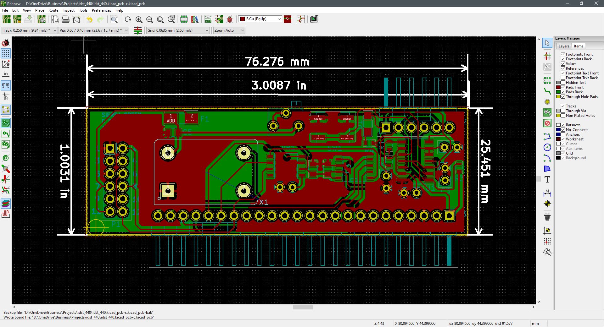
Completed first build of revision A. The new PCB fabrication company turns out okay so far. Comes from the U.S., less money and faster delivery. I still have to debug the hardware and look for flaws. Initial tests show functionality, but there are component values that probably need attention. Plus the need for a jump or two.

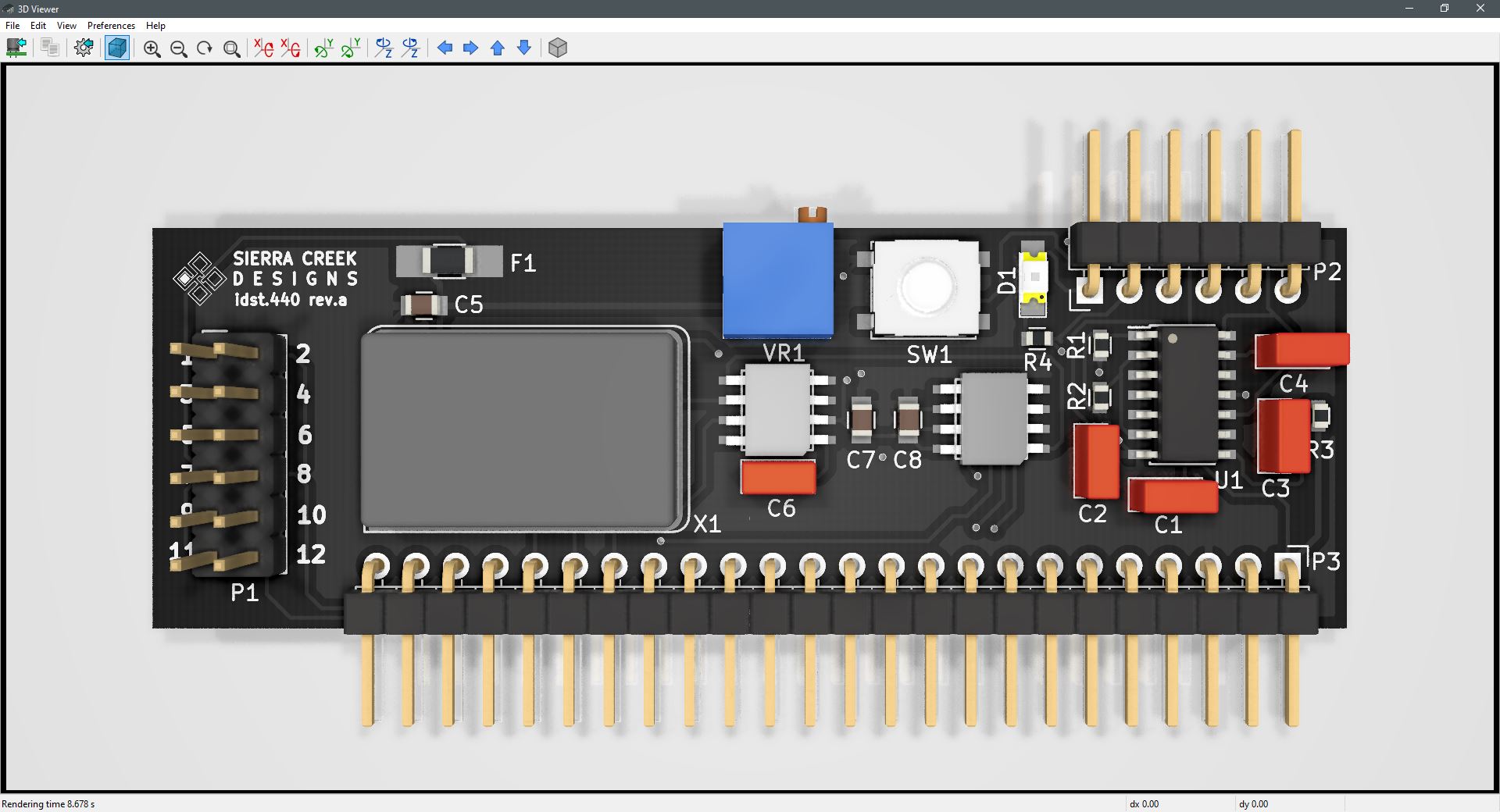
The blue trim control is for duty cycle variable control and the momentary switch-button sends a one-shot pulse to the output header. The second pass will be with an Arduino SBC to control its output clock speed.

Micro slot module test and debug.

Prototype Micro-Slot Module & Proof of Concept

Unraveling nested nodes to get the prototype unit fabricated and built. It’s inevitable, jumps and via’s shall be sprinkled throughout to overcome the entanglements. This is the first micro slot module among others to follow. A sort of proof of concept to arrange a vertically mounted assembly that inserts into base station modules that host SBCs.

Suitable for socketed on perforated boards as well to accommodate prototyping or one-and-done projects. The idea is to set a template project for modules overall whereas time to completion is accelerated from idea to development and completion. The framework by which originated or reference design materials is dropped-in to become far easier to implement with more attention placed upon interface or code requirements to satisfy intended functions.


Programmable Pulse Timer Concept & Design

As more circuit builds come about, they’re increasing in density. Bought the parts. Gerber files, drill codes and netlist off to the fabrication house now. The programmable timing module design is finished. With hardware debugging ahead a few minor adjustments are expected once results are validated. This is a mixed-mode project where both plated through-hole and surface mount components are applied.

In a micro-slot format, this is a module intended for use in a free-standing application. With pulse speed and duty cycle setting completed manually via jumpers and a trimmer, separate outputs are assigned to independent and isolated pins at the micro-slot header.

Here is a tentative sketch of what it looks like.