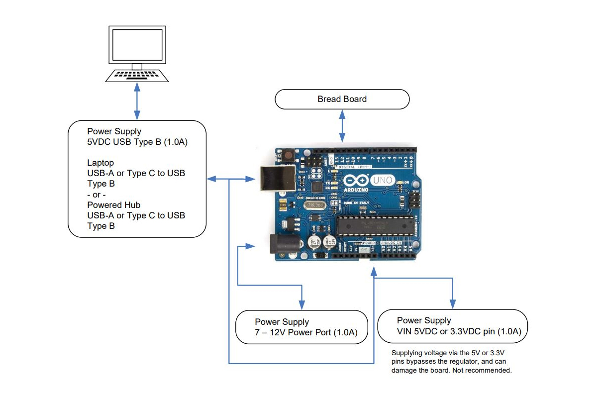
As previously posted with the RPi set up, the same is illustrated here but for Arduino Uno. A very common single board computer that is entry level and simple to set up and operate
As before, three areas of interest are given.
Block Diagram Pin Out Diagram Tool Chain
The purpose of each work together to build hardware and software controller applications that operate with a host or in a freestanding manner.
While Arduino is widely understood as an entry-level SBC, it can be found among enthusiasts, makers, and project minded people who wish to build projects and code them for unique applications. Centered on the ATMega microcontroller, the software support is deep in a large community of developers. The development environment is an IDE appropriately named Sketch.
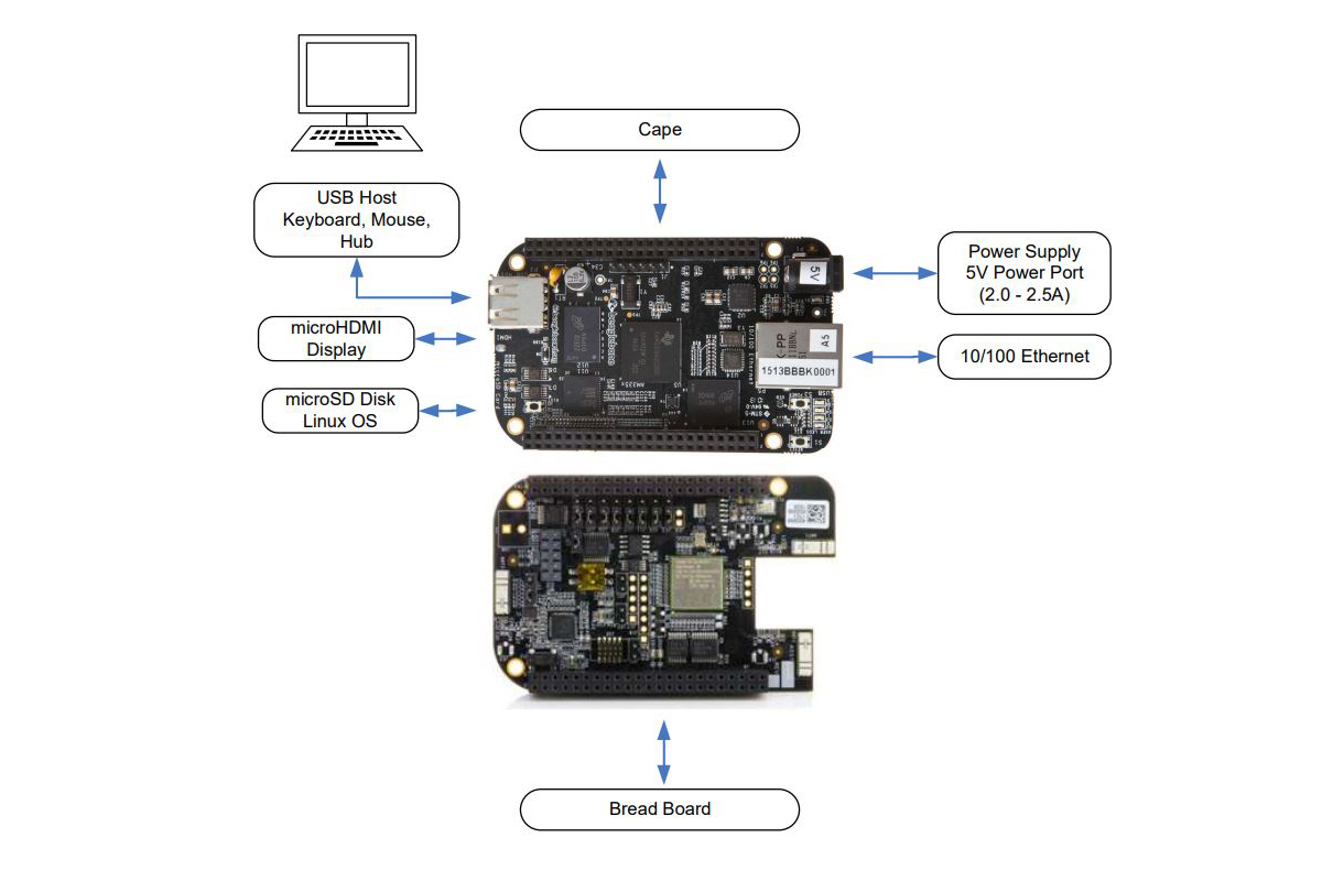
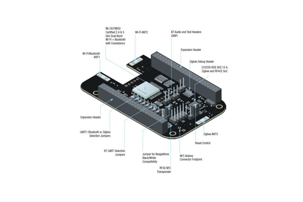
This is the third set up posting for an SBC system. This time it is for the Beagle Bone Black with a wireless cape. The attached PDF and diagrams posted here provide a suitable reference for a project in terms of hardware and software development. While there are a number of illustrations and diagrams of interest here, there is also an excellent text by Derek Molloy that offers a more comprehensive look at the setups to support projects of numerous types (ISBN 978-1118935125).
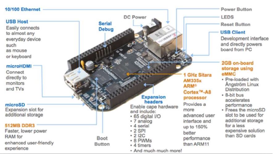
As previously posted with the RPi and Arduino Uno setups, the same is illustrated here but for BeagleBone Black. A very common single-board computer that is entry-level and simple to set up and operate. Widely known among makers, academics, and students for control automation, robotics, and sensor/actuator processing applications.
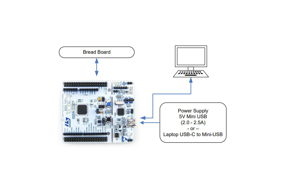
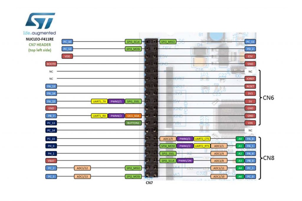
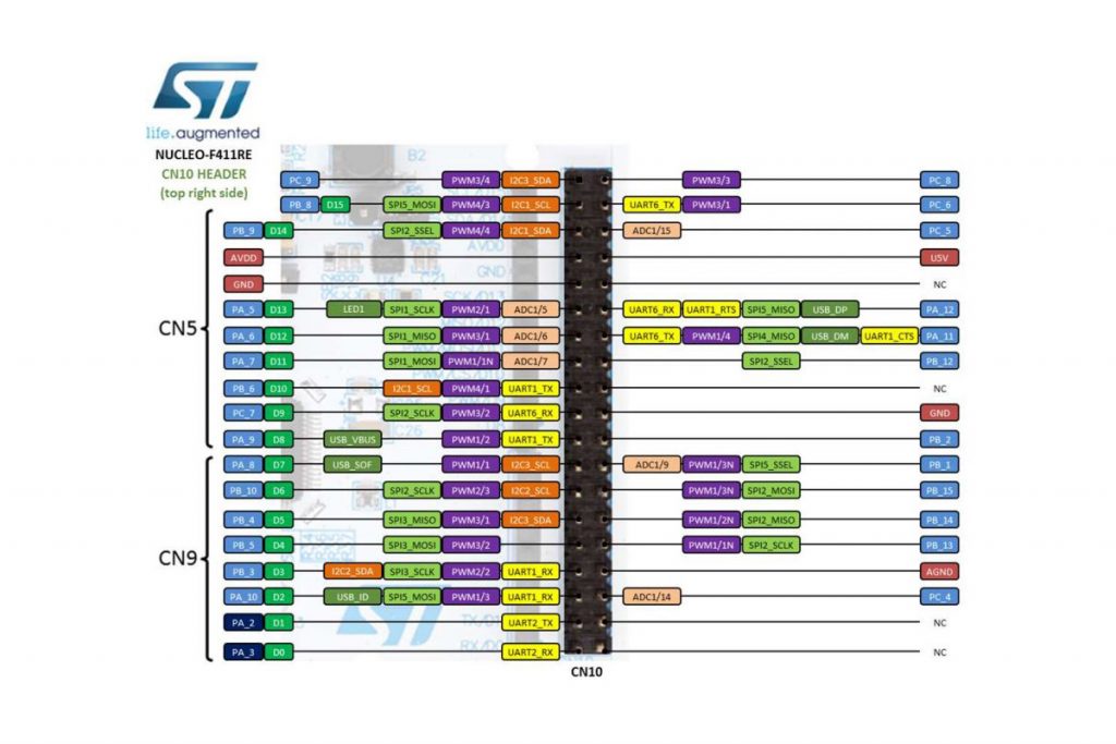
The ST Micro Nucleo single-board computer (SBC) provides for both analog and digital ports that offer more flexibility toward projects developed. In terms of its physical hardware set up, it is probably the easiest to bring together as compared to other more common SBC solutions.
The Nucleo board is supported by the mbed development system. An online code editor to produce applications for a wide range or project types. The SBC largely provides for a USB interface, power, clock and general purpose I/O in a small form factor.
It can operate with a host or as a freestanding board for set and forget applications. Largely to compete with Arduino, but also for development support of STMicro controller ICs which involve evaluation, qualification for suitability, etc.
As a way to set a reference about how Raspberry Pi gets set up for repeated and continued use, it makes sense to identify system components in one place. Altogether for ease of use and assembly. This diagram is a way to identify hardware and possible software elements for development and exploration.
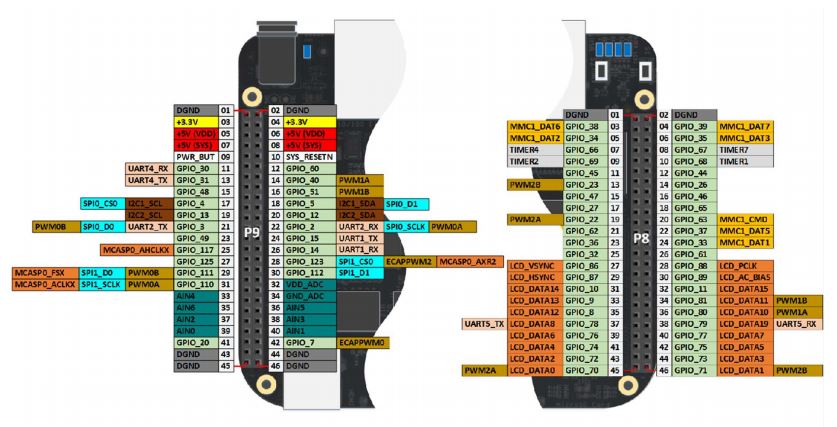
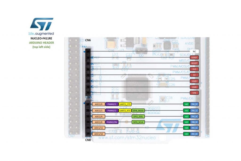
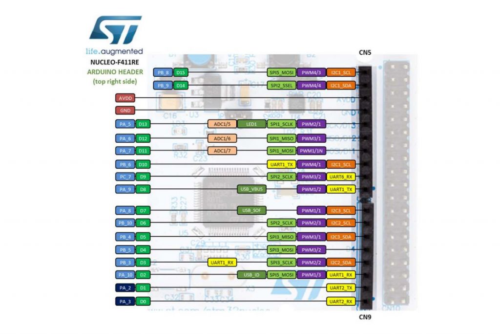
More specifically, a block diagram is illustrated to indicate where various interfaces apply. Display ports, power, general-purpose I/O, USB, and so on. Since peripheral connectivity is quite large with the 40-pin dual inline connector, a pin-out diagram is also illustrated here. Each pin having its reference number and name to describe its purpose.
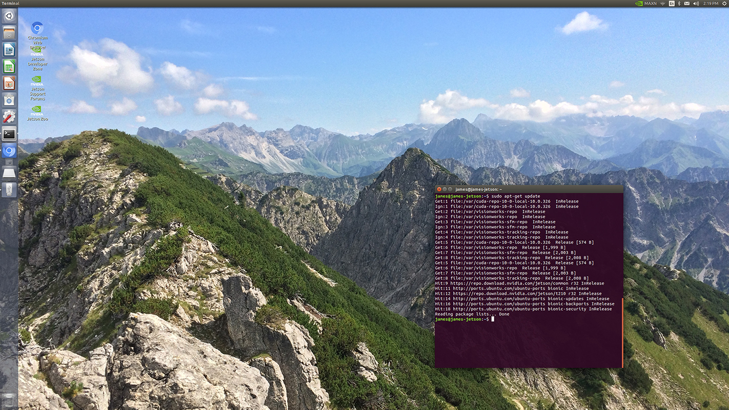
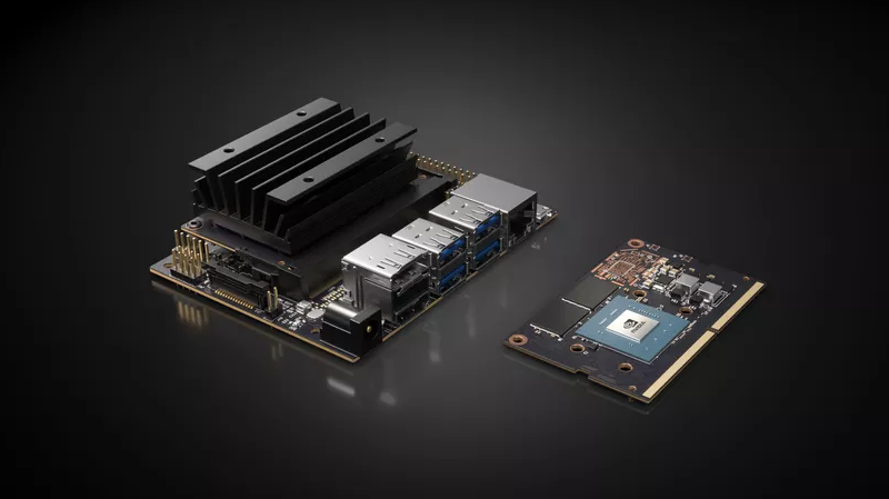
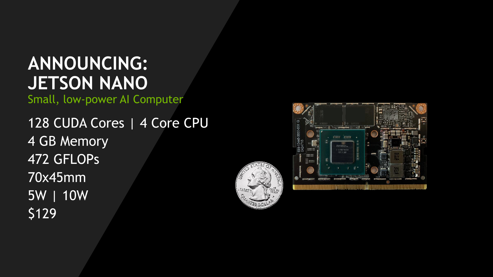
The Jetson Nano AI system set up was completed in preparation for various projects ahead. The process was very involved as it included the physical construction of the AI system hardware to also correspond to the associated Linux OS and GUI (Ubuntu). All configurations were completed such as the necessary Linux and Ubuntu applications. To set up the operating system with a new microSD card, 128GB is recommended for plenty of capacity. To format the microSD card, download the SD card utility from the sdcard.org site and install it to initialize the card. Once the card is formatted, download and install the operating system image from the NVidia Jetson nano developers website. To install the selected image, install and use the balenaEtcher utility. The image file from NVidia remains in its compressed format (zip file) as installed onto the microSD card. Once the MicroSD card is ready, insert it in the Jetson Nano and boot up the system.
Once the system is up and running, open a terminal window to execute a sudo apt-get update to get the necessary Linux package updates. Thereafter, update the Ubuntu application itself as well.
It is certain that additional language setups are required as well such as Python and OpenCV.
There are numerous programs that will get written and made operational to involve object and facial detection, sensors, actuators, and so forth. In the days, weeks, and months coming various projects make use of this set up as a common platform of progress and advancement.
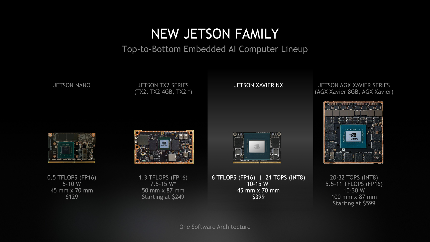
The Jetson Nano AI operating system originates from NVidia for developers to originate applications in deep learning and artificial intelligence. To that end, following posts after set up and configuration incrementally move towards grow and new discover.
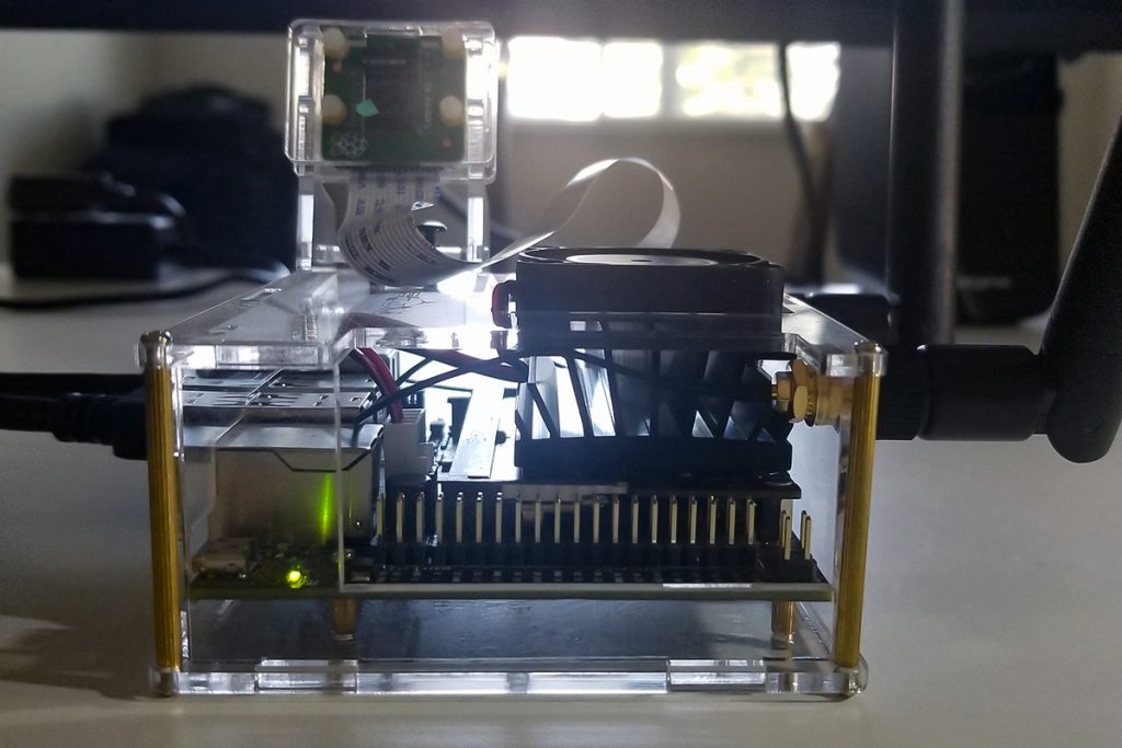
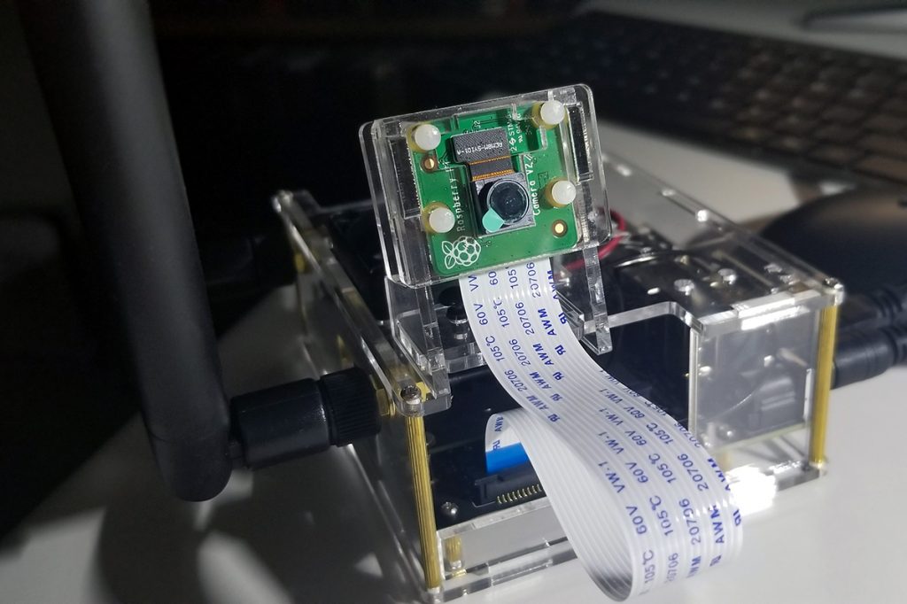
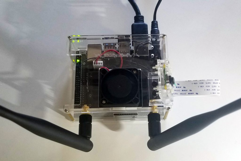
Linux OS with Ubuntu Environment
Linux Operating System Ubuntu with NVIDIA GPU support. Superior graphical processing power necessary for camera sensor image capture, collection, and instruction handling. External Header for GPIO Port Interface ConnectivityRaspberry Pi Camera with Ribbon Cable ConnectivityWIFI Antennas (external / optional capability with expansion card), Cooling Fan, Clear Acrylic Case, and Connections. To include HDMI, 10W Power Receptacle (5VDC 4A wall adapter), RJ45, USB-A and USB-B Micro ports.
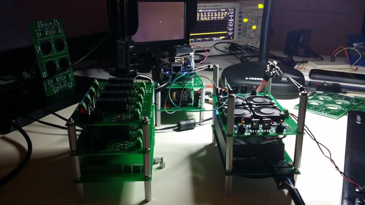
This is the thermal management module stacked upon other free-standing modules. Each module that operates on its own, or together in an integrated fashion. With a small SBC based micro tower computer built from scratch (RPi), power, cooling, processing, sensor adaptation, and load control all integrated together perform functions in a stackable format.
These modules are interchangeable in terms of position and somewhat by function. There is a functional modularity that extends to other modules built together or separated to deliver isolated capabilities unique to various use-cases. Namely, cooling functionality, power support, and programmability with sensor integration. Other functions associated with common SBCs with GPIO ports include relays, actuators, sensors, drivers, routers, etc.
Tonight’s successful concept test with Python conversion from Arduino to Raspberry Pi. Happened to find the experimental Arduino code to drive an external sensor module. For it to behave as it should and provide acknowledgment and function as expected. It is often better to work with Arduino with available analog ports as compared to RPi with only digital ports.
This exercise served as an example of how to port code over from one platform to another. With necessary and simple edits unique from each area of operation.
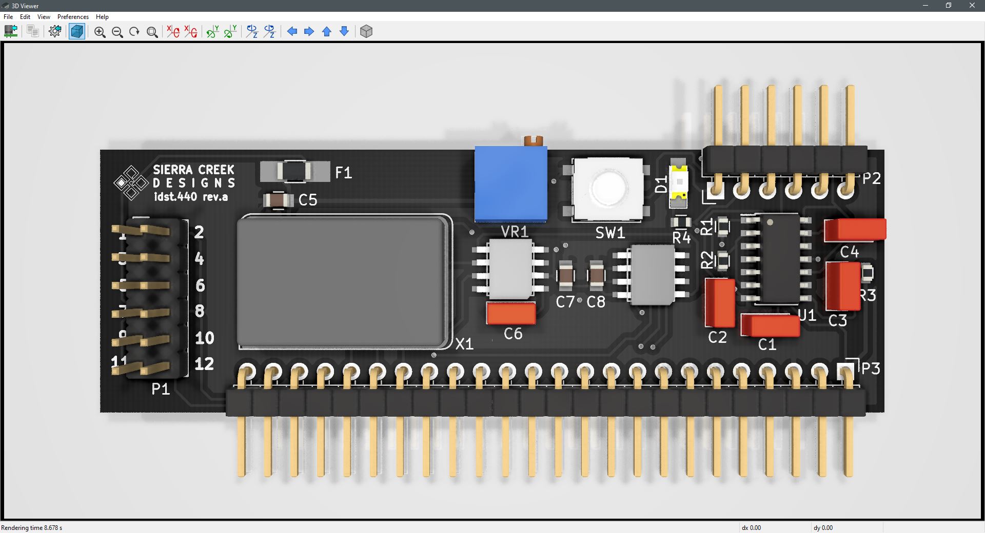
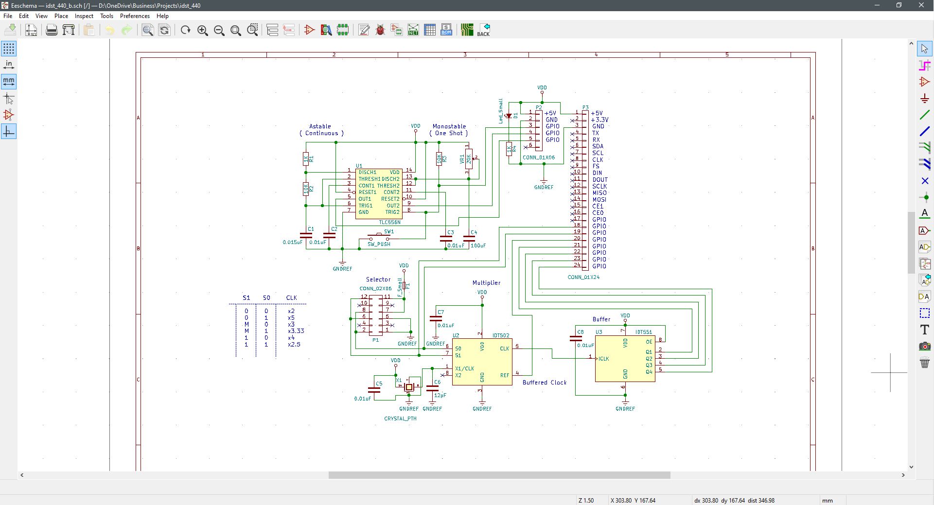
Completed first build of revision A. The new PCB fabrication company turns out okay so far. Comes from the U.S., less money and faster delivery. I still have to debug the hardware and look for flaws. Initial tests show functionality, but there are component values that probably need attention. Plus the need for a jump or two.
The blue trim control is for duty cycle variable control and the momentary switch-button sends a one-shot pulse to the output header. The second pass will be with an Arduino SBC to control its output clock speed.
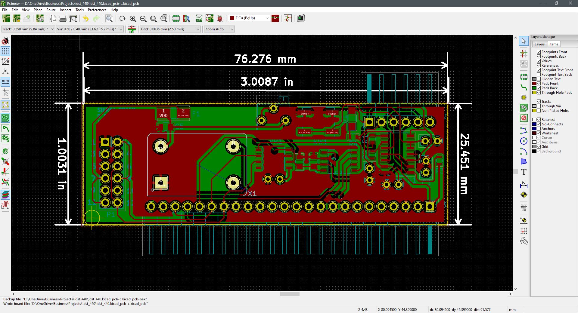
Unraveling nested nodes to get the prototype unit fabricated and built. It’s inevitable, jumps and via’s shall be sprinkled throughout to overcome the entanglements. This is the first micro slot module among others to follow. A sort of proof of concept to arrange a vertically mounted assembly that inserts into base station modules that host SBCs.
Suitable for socketed on perforated boards as well to accommodate prototyping or one-and-done projects. The idea is to set a template project for modules overall whereas time to completion is accelerated from idea to development and completion. The framework by which originated or reference design materials is dropped-in to become far easier to implement with more attention placed upon interface or code requirements to satisfy intended functions.
As more circuit builds come about, they’re increasing in density. Bought the parts. Gerber files, drill codes and netlist off to the fabrication house now. The programmable timing module design is finished. With hardware debugging ahead a few minor adjustments are expected once results are validated. This is a mixed-mode project where both plated through-hole and surface mount components are applied.
In a micro-slot format, this is a module intended for use in a free-standing application. With pulse speed and duty cycle setting completed manually via jumpers and a trimmer, separate outputs are assigned to independent and isolated pins at the micro-slot header.
Here is the power supply I made from scratch to support the various modules developed so far. With more to come, this unit is sure to prove useful again and again. A fundamental layer module for various units that are developed; both analog and digital.
This is a power supply module with +/- 15V and +5V output ports. The module hosts a low-profile switching power supply (SPS) soldered and bolted in place for high board retention. At the output of the module is a screw-locking terminal strip for each available voltage point. To include reference designators as printed on the circuit board for ease of identification and termination. The power LED illuminates as an AC input voltage is applied.
An AC source voltage is supported with a male 3-point plug-detachable receptacle for a 115VAC 60Hz input. This unit comes with a matching male plug for safe and fully insulated AC connectivity. The module is fitted with a 3A circuit breaker that provides added protection between the SPS and its source.
This is a video walk-through about a 4-channel contact closure relay module I made. An example application is demonstrated here by driving a micro-fan through a relay and connector signal path via a remote and physically isolated contact closure made at an input. There are many applications by which this module will prove both practical and useful.
It serves as a way to achieve a high-current path closure by simply providing a shorted connection at each input.